


 Chinese
 Spanish
 Russian
 Portuguese
 French
 German
 Indonesian
 Thai
 Vietnamese
 Arabic
 Italian
 Turkish
 Polish
 Japanese


Load Cells
Selecting Hints
Compare METRAVON load cells for tanks, silos, platforms and equipment. Check load direction, capacity, mounting, signal conditioning and acceptance before inquiry.
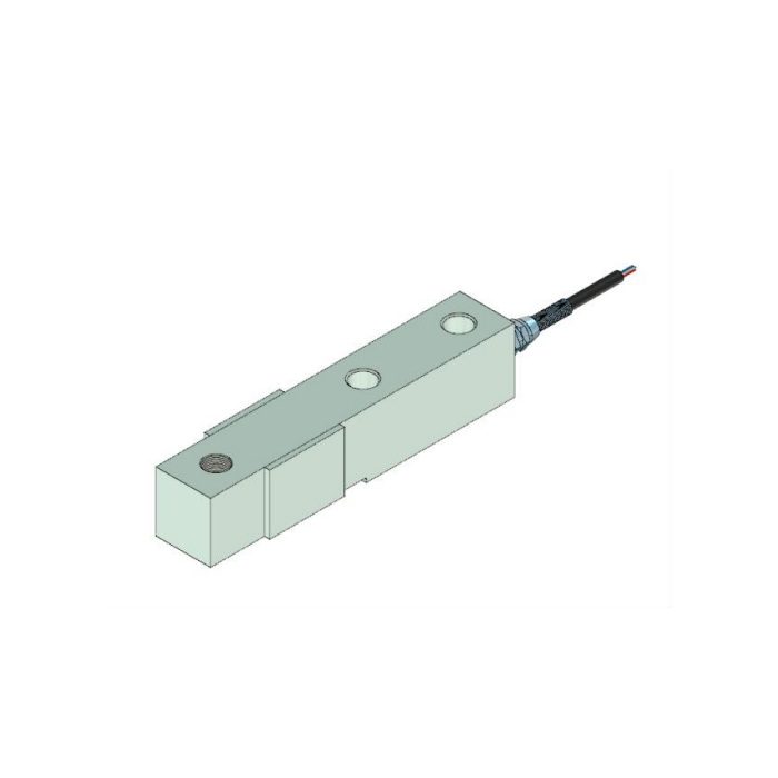
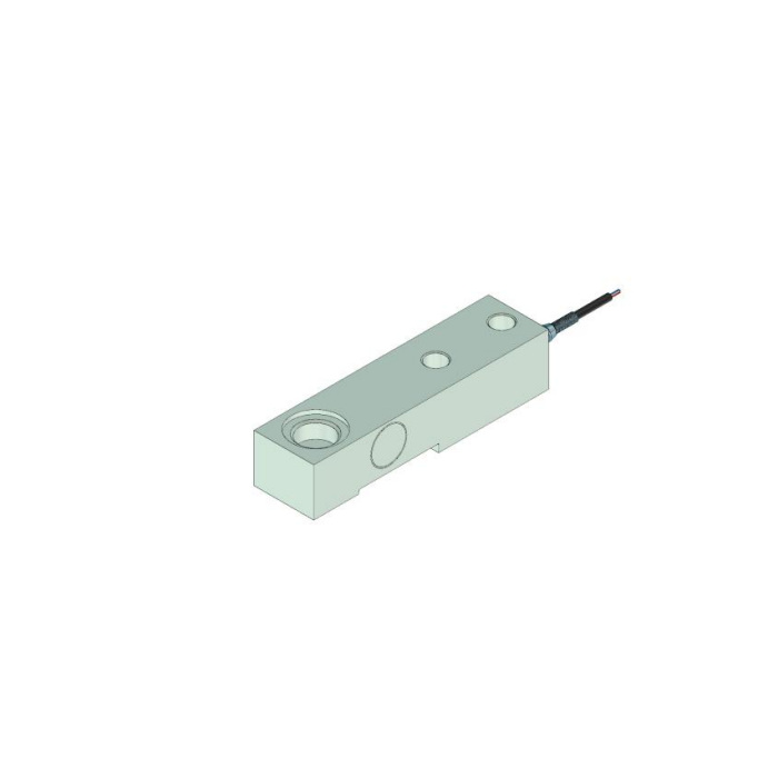
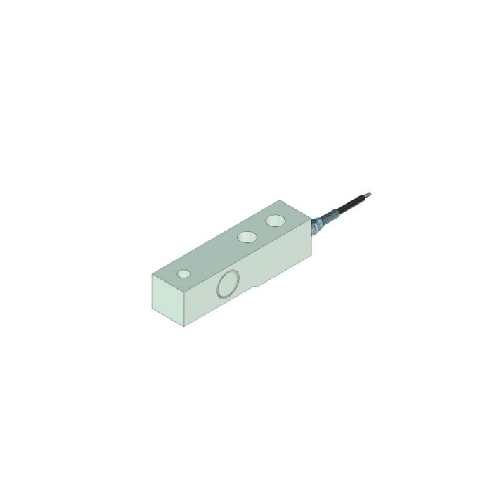
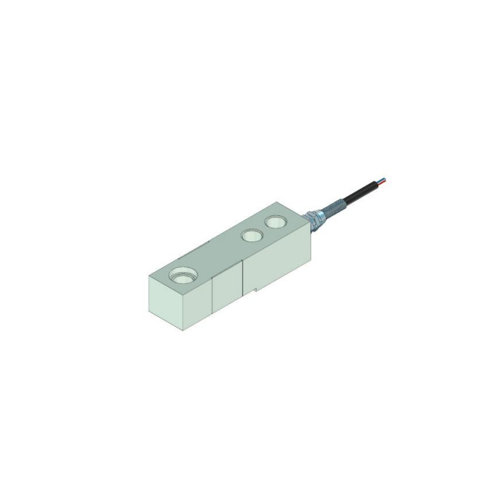
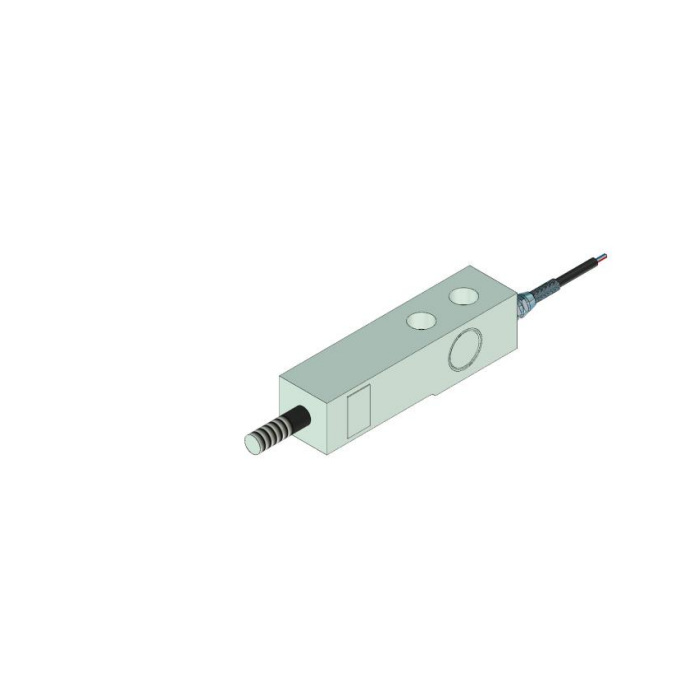
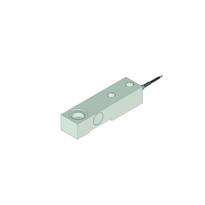
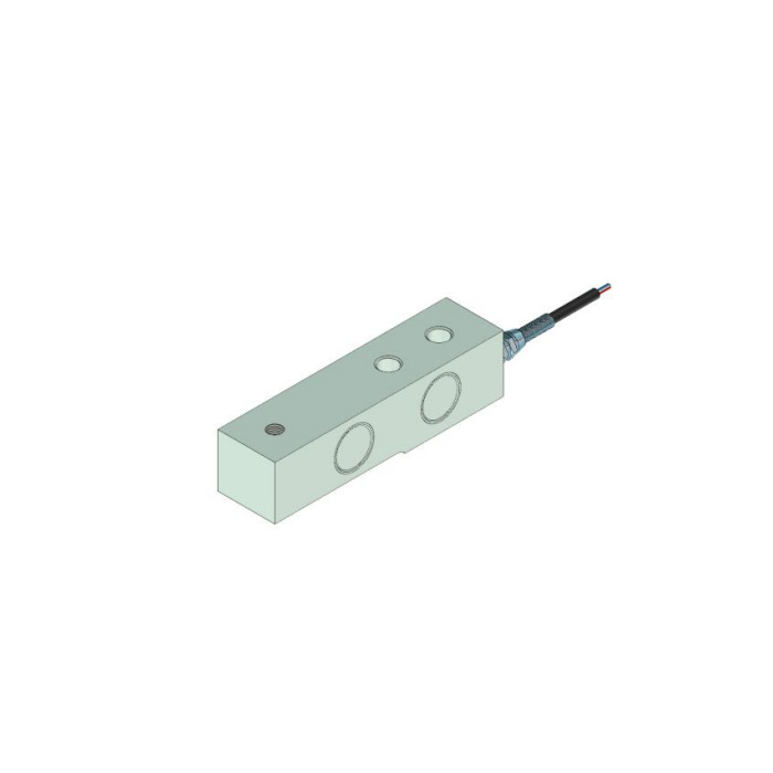
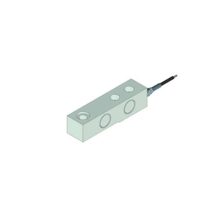
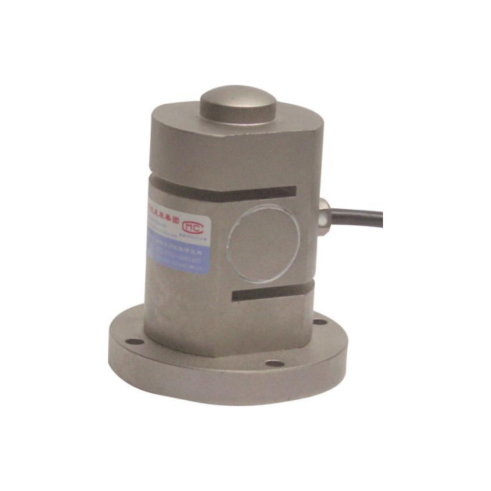
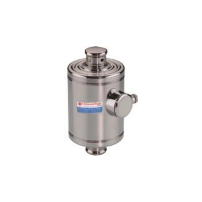
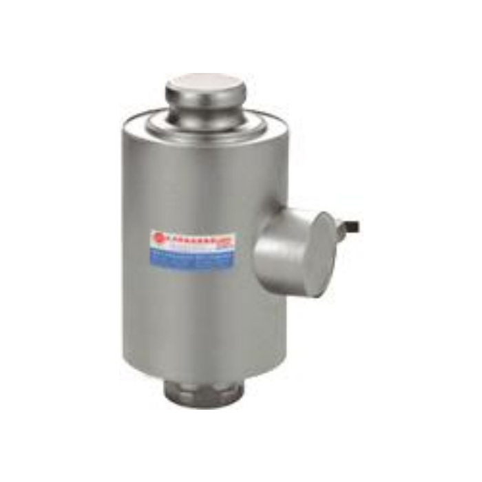
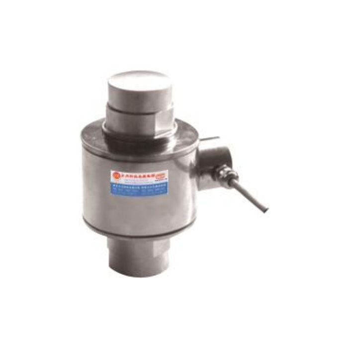
Select the Load Cell from the Force Path
Capacity is only one selection input. First identify whether the force is compression, tension, tension and compression, shear or multi-axis. Then compare the mounting envelope, load introduction, side loads, overload risk, cable routing, environment and the instrument that will excite and read the sensor.
| Structure | Typical engineering use | Critical checks |
|---|---|---|
| Compression column or button | Compression measurement where the load can be introduced concentrically. | Bearing surfaces, alignment, lateral restraint, capacity per support and overload during installation. |
| Cantilever or shear beam | Platforms, hoppers and process weighing assemblies with a defined mounting arrangement. | Fixed and loading ends, mounting bolts, load direction, corner loading and available clearance. |
| S-type or tension/compression | Suspended loads, test equipment and applications requiring axial tension or bidirectional force measurement. | Thread and attachment geometry, rod-end alignment, bending and tension/compression calibration direction. |
| Load pin | A structural pin is replaced by a sensing pin in a clevis, sheave or joint. | Pin diameter and length, bearing positions, anti-rotation, cable exit and the actual shear planes. |
| Multi-axis force sensor | Projects that must resolve more than one force or moment component. | Axis definition, cross-axis loading, mounting stiffness, channel count and data-acquisition compatibility. |
Signal Chain and Acceptance
Do not assume that every load cell sends 4-20 mA or RS485 directly. When the selected sensor provides a millivolt-per-volt bridge signal, the connected weighing indicator, transmitter or acquisition module must supply the correct excitation, sensitivity range, calibration functions and output required by the PLC or RTU.
- Submit the maximum and minimum load, force direction, support count and drawing or installation photographs.
- Match dimensions, mounting pattern, cable arrangement and environmental conditions before confirming electrical compatibility.
- At commissioning, record zero, known-load response, repeat loading, unloading, corner or support balance where applicable, and the final control-system value.
- For replacement work, compare the old datasheet, wiring, sensitivity, rated capacity and calibration method rather than matching the housing alone.
For tanks and hoppers that need restraint and load-introduction hardware, review weigh modules. For display, calibration and PLC output requirements, review weighing indicators.
Please fill in the measurement media, the scale, temperature, pressure, installation and output requirements. We will provide model advice and quotations based on the field situation.
