


 Chinese
 Spanish
 Russian
 Portuguese
 French
 German
 Indonesian
 Thai
 Vietnamese
 Arabic
 Italian
 Turkish
 Polish
 Japanese


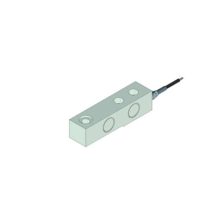

METRAVON MV-LC0044 is a cantilever load cell with a recessed load-end seat in its reference outline. The beam is listed for a technical interval of 0-5 t, with a 137 mm body-length reference. The recess and lower opening need a matched load-transfer part, not a fitting selected only because it enters the hole. For low-profile frames and hoppers, show that contact together with the fixing end and underside clearance before confirming the assembly.
Match the cantilever load cell recessed seat to its contact part
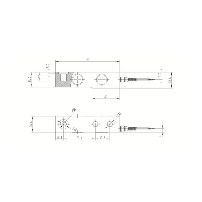
The load-end view gives a 26 mm outer recess and a 16 mm inner opening, with a 4.2 mm recess-depth annotation in section. A further 24 mm vertical reference appears at that end. Obtain the complete toleranced seat and mating-part drawing before deciding which surfaces bear and which merely provide clearance. The opening is diameter-labelled, not a confirmed threaded connection. Neither the recess depth nor the visible circular geometry specifies a permissible pin fit, tightening torque or lateral-load allowance.
Check the fixing pattern and the full lower contact arrangement
The plan-width reference is 36.6 mm. The load-end centre has an 18.4 mm end offset, followed by a 76.2 mm spacing to the first fixing position; the paired diameter-13 fixing holes are 25.4 mm apart. The side view shows 34.5 and 36.6 mm vertical references and a separate 59 mm lower length. Confirm the intended fixed-end supporting surface rather than adding a continuous packing strip below the whole beam. The relieved underside must not gain another load-bearing contact as the frame moves.
| Item | Value | Selection notes |
|---|---|---|
| Body length / plan width | 137 / 36.6 mm | Check both height references and the actual supporting faces. |
| Load-end outer / inner feature | 26 / 16 mm | Diameter references do not establish a thread or an approved pin fit. |
| Recess-depth annotation | 4.2 mm | Use the complete section with the mating load-transfer part. |
| End offset / next centre spacing | 18.4 / 76.2 mm | Retain the actual load-end and fixed-end roles. |
| Fixing holes / paired spacing | Two 13 mm holes / 25.4 mm | Confirm the supporting footprint and fasteners separately. |
| Lower length reference | 59 mm | It is not permission to support every visible lower surface. |
Describe the largest local reaction and the small weight changes that matter
Provide frame or vessel tare, maximum contents and any uneven support loading caused by the actual layout. A forklift or hopper application reference is not an approval for every bracket or pipe connection. Specify the useful net interval and required installed readings, especially where a substantial dead load is present. The 0.05% FS precision entry applies on a full-scale basis. The 150% FS safe-load entry cannot be used as a rated load for a locally made seat or as a general overload-test instruction for the structure.
Confirm the bridge and temperature interval for the chosen rated version
The channel uses 2.0 +/-0.002 mV/V at 10-12 V DC excitation, with 380 +/-5 ohms input and 350 +/-1 ohm output resistance. The reference lists 6 m of cable. Use the delivered wiring record to resolve the conflicting reference signal-colour list and circuit. Temperature compensation is specified over -10 to +65 deg C, while operation is listed over -40 to +85 deg C. Define the expected sensor temperature and weighing acceptance without treating the whole operating interval as one compensated measurement specification.
Accept the frame after the final recessed fitting is in place
Inspect the fixed end, seat, lower relief and cable restraint before correcting zero. Apply agreed reference weights through the actual load head and compare loading, unloading return and any relevant support positions. If changing a guide or cable restraint changes the indication, examine the contact path before changing span. For IP68, obtain the delivered sealing details and expected exposure conditions, including the junction location. The technical range alone does not prove that every offered rating shares this reference geometry or that a replacement can retain all old contact parts.
Compare the MV-LC0045 smaller load-end opening if the retained fitting does not match this recess. The comparison is about contact geometry; it does not establish a direct replacement from the common body length.
Recessed seats and retained contact parts
Q1. Can a plain pin be selected just from the 16 mm opening?
The complete seat includes the larger recess and its contact geometry. Obtain the allowed fit, bearing faces and retention method for the offered assembly. A pin that enters the opening is not automatically a suitable load head.
Q2. Is it a direct replacement for another 137 mm-long beam?
A shared length does not establish the same load-end opening, fixing pattern, contact height or support footprint. Compare the actual rated sections and signal channel. A replacement should retain old hardware only where those interfaces are confirmed.
Q3. Which drawings are needed to quote a low-profile frame?
Send the seat and mating-part section, base pattern, available height and lower clearance, with maximum reaction and useful net weights. Include the reader and exposure conditions. Ask the offer to identify the beam and every required contact part separately.
