


 Chinese
 Spanish
 Russian
 Portuguese
 French
 German
 Indonesian
 Thai
 Vietnamese
 Arabic
 Italian
 Turkish
 Polish
 Japanese



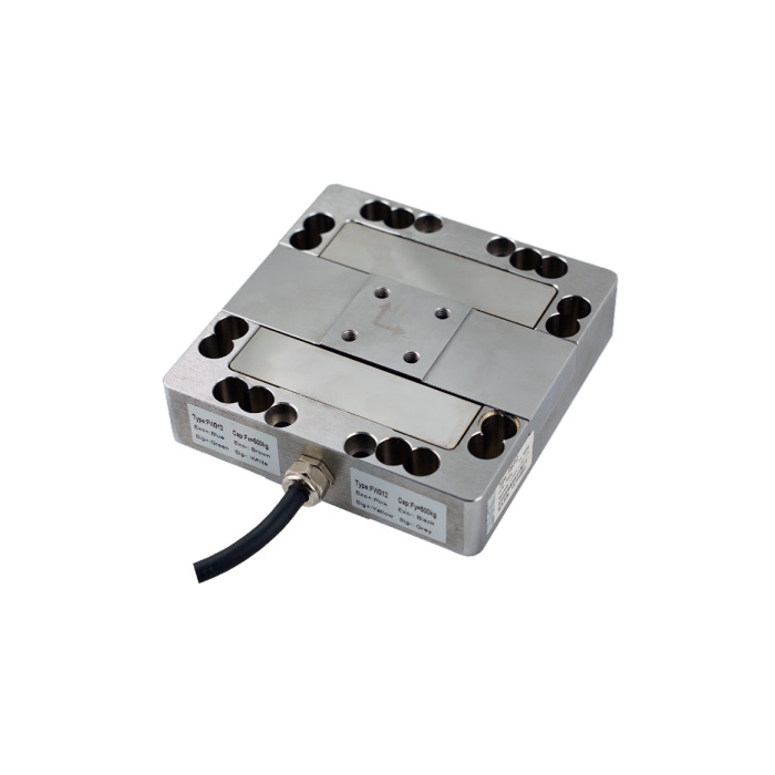
The METRAVON MV-LC0240 three-axis force sensor measures Fx, Fy and Fz through separate bridge circuits. Its square mounting arrangement is a candidate for fixture tests that need to observe the direction of an applied force. Select it from the three component loads and the required resolution of each component, rather than treating it as one conventional weighing channel.
Read the axis ratings and crosstalk together
The catalogue gives a 500 kg capacity designation for each axis. Because these are force channels, agree the calibration units and scaling with the order. Do not turn the capacity label into a software conversion without the applicable calibration record.
| Item | Listed value | Fixture check |
|---|---|---|
| Fx, Fy and Fz ratings | 500 kg per axis | Submit the three forces acting together and any moments introduced by the fixture. |
| Rated output | 1.0 mV/V +/-10% | Calibrate each channel rather than copying one nominal gain across the acquisition system. |
| Force crosstalk | 2% F.S. | Review whether a small component can be resolved while a much larger force acts on another axis. |
| Non-linearity | +/-0.2% F.S. | Assess the complete error allowance with coupling, mounting and acquisition effects included. |
| Excitation and connection | 5-12 V DC; 12-pin connector | Check the supplied axis-by-axis pin assignment and the connected bridge input capacity. |
| Protection | IP65 | Confirm cable and connector protection for the actual cabinet or machine environment. |
The drawing shows a 120 x 120 mm mounting envelope with separate fixing features for the supporting structure and loaded fixture. Use the dimensioned drawing to identify those interfaces. A bolt position that fits the envelope may still constrain the sensing structure if the wrong surfaces are clamped.
Keep the coordinates consistent through acquisition
Mark the positive axis directions on the machine drawing and preserve them in the channel names, calibration file and reported results. A rotated installation can produce plausible numbers in the wrong coordinates. If a resultant force is required, establish the channel signs and sampling relationship before calculating it.
During acceptance, apply agreed reference loads along the required directions and record all three outputs for each load case. This reveals reversed wiring and cross-axis response that a single-channel check can miss. Include fixture tare and repeat loading after the final mounting is tightened.
Three-axis measurement questions
Q1. Will one ordinary weighing indicator read all three forces?
A single bridge input does not provide three independently measured components. Specify three suitable bridge channels, their excitation arrangement and the sampling relationship required by the test. Confirm that any common supply and input connections are permitted by the delivered wiring diagram.
Q2. Does the 2% crosstalk figure define the overall test accuracy?
It describes coupling between force channels, not the complete uncertainty of a loaded fixture. Where a small lateral force is measured alongside a large axial load, request the applicable calibration and compensation method and validate that load combination.
Q3. Are bending moments and torque measured independently?
MV-LC0240 provides three force components. If the test also needs separate moment outputs, examine a six-axis force/torque sensor and submit the complete force and moment envelope.
An inquiry should include the fixture section, expected Fx/Fy/Fz loads, offsets, required units, acquisition channel details and the smallest force change that must be resolved. Use the quotation form to state those requirements with the operating environment and calibration scope.
