


 Chinese
 Spanish
 Russian
 Portuguese
 French
 German
 Indonesian
 Thai
 Vietnamese
 Arabic
 Italian
 Turkish
 Polish
 Japanese



METRAVON MV-LC0241 is a six-axis force/torque sensor for Fx, Fy, Fz, Mx, My and Mz measurement. The force and moment ratings are offered in matched sets. Choose a complete set around the application's loads, then review the fixture geometry and acquisition system needed to preserve those six components.
Select a complete force and moment rating set
The following rows keep the published force and moment combinations together. They are not interchangeable menu choices for building an unverified configuration. The allowable combination of simultaneous loads still requires review.
| Fx/Fy and Fz | Mx/My | Mz |
|---|---|---|
| 2 kN / 10 kN | 150 N m | 150 N m |
| 5 kN / 25 kN | 350 N m | 250 N m |
| 10 kN / 50 kN | 700 N m | 500 N m |
A force applied away from the sensor reference creates a moment. Include the distance to the tool or load application point, the mass of attached equipment and operating transients in the load submission. Six individual nameplate limits do not by themselves define an acceptable combined-load envelope.
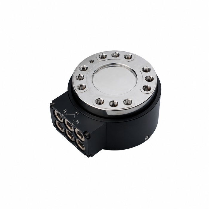
Specify the six bridge channels before choosing the data system
The listed outputs are mV/V bridge signals with different nominal sensitivities. The receiving equipment needs suitable excitation, low-level inputs and a defined calibration process. A connector count or a generic analog-input specification cannot establish those functions.
| Channel or item | Listed value | Wiring check |
|---|---|---|
| Fx/Fy sensitivity | 1.5 +/-0.3 mV/V | Use the delivered channel calibration rather than nominal sensitivity alone. |
| Fz sensitivity | 1.3 +/-0.3 mV/V | Keep its gain and engineering units separate from the lateral channels. |
| Mx/My sensitivity | 1.4 +/-0.3 mV/V | Identify bending axes and their signs on the fixture drawing. |
| Mz sensitivity | 1.2 +/-0.3 mV/V | Check the torsional reference and the convention used in recorded results. |
| Reference excitation | 10 V AC/DC | Verify the delivered circuit and conditioner; the maximum listed excitation is 15 V AC/DC. |
| Operating limits | -20 to +65 deg C; IP65 | Review the installation exposure and the -10 to +40 deg C compensated temperature range. |
Obtain the terminal and connector schedule for the delivered assembly. Agree whether calibration includes a coupling matrix, how the data system applies it and which coordinate transformation is required at the application. Sampling rate, dynamic response and software support need explicit confirmation for a time-dependent test; they cannot be inferred from static force ratings.
Six-axis test planning
Q1. How should a multi-axis installation be checked?
Document the unloaded fixture state and apply reference load cases with known directions and application points. Record all six channels, verify signs and units, and compare the results with the agreed calibration method. Include the final adapters because their offsets change the moments at the sensor.
Q2. Does a 150% safe overload specification permit every axis to reach that value together?
No combined-load permission follows from that percentage. Submit the simultaneous forces, moments and transients for review. Establish mechanical protection and the approved operating envelope before the sensor is installed.
For an MV-LC0241 quotation, provide the matched rating set, fixture and coordinate drawings, peak load cases, required sampling behaviour, acquisition hardware and calibration deliverables. If the application needs only Fx, Fy and Fz, compare the MV-LC0240 three-axis arrangement against that narrower measurement task.
