


 Chinese
 Spanish
 Russian
 Portuguese
 French
 German
 Indonesian
 Thai
 Vietnamese
 Arabic
 Italian
 Turkish
 Polish
 Japanese



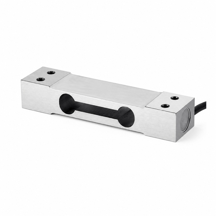
METRAVON MV-LC0243 is an extended-length parallel beam load cell with a listed 5-50 kg capacity range. The bending-beam arrangement has one fixed end and one loaded end. It is a candidate for compact platform, hopper or packaging-scale designs where the support geometry can introduce the load through the intended end without constraining the active beam.
Fit the long beam into the scale's mechanical load path
The nominal body dimensions are 130 x 30 x 22 mm. Compare the full mounting drawing with the base, load receiver and available cable clearance; the overall length alone does not establish a replacement. Provide the fixing-hole layout and the proposed loading attachment before confirming an assembly.
Include the load receiver's dead weight when choosing a rating. Filling impact, eccentric application and mechanical restraint can change the force reaching the beam. A larger nominal capacity is not a substitute for correcting a platform that touches its surround or a hopper connection that carries part of the load elsewhere.
| Item | Listed data | Use in design |
|---|---|---|
| Capacity range | 5-50 kg | Confirm the offered discrete rating with the platform dead load and operating load included. |
| Output sensitivity | 2.0 +/-0.05 mV/V | Match the excitation and input span of the connected weighing instrument. |
| Bridge resistance | Input 380 +/-30 ohm; output 350 +/-5 ohm | Check the combined excitation load if more than one sensor is connected. |
| Excitation | 5-12 V | Use a compatible bridge supply rather than applying a PLC analog-input supply by assumption. |
| Temperature and protection | -20 to +70 deg C; IP66 | Review the selected material and cable sealing against the installation environment. |
Inspect the assembly before adjusting the indicator
- Check that the base and load receiver use the designated mounting regions and do not clamp the active beam section.
- Inspect clearances through the intended travel so the platform, stops and surrounding structure cannot bypass the measurement path.
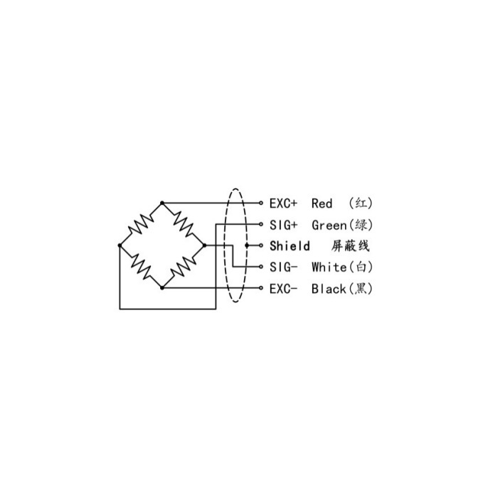
- Route the cable with strain relief and enough clearance for the weighing movement; follow the instrument's shielding and bonding instructions.
- Set the zero with the completed empty assembly, then verify known loads, unloading and repeatability at the required load positions.
The bridge needs a compatible weighing indicator or transmitter for excitation and calibration. With a nominal 2 mV/V sensitivity, 5 V excitation gives about 10 mV at rated load. The installed dead load consumes part of that electrical span, so the indicator input and the usable weighing range should be reviewed together.
Parallel-beam installation questions
Q1. Should both ends be fixed rigidly to the same base?
The specified arrangement fixes one end and introduces the measured load at the other. An assembly that ties both ends to the same rigid base can prevent the intended bending response or create an unintended force path. Follow the approved mounting drawing rather than copying the outline of an old sensor.
Q2. Does 150% safe overload increase the weighing range?
The 150% F.S. figure is a protective load specification. Measurements and normal service loads must remain within the approved rated range. Design overload protection and installation handling around the complete scale rather than using that percentage as an extra operating allowance.
For an MV-LC0243 quotation, provide the platform or hopper drawing, dead load, maximum contents, load positions, operating cycle and indicator details. Include the required calibration method and the material or cleaning conditions that affect the ordered version.
