


 Chinese
 Spanish
 Russian
 Portuguese
 French
 German
 Indonesian
 Thai
 Vietnamese
 Arabic
 Italian
 Turkish
 Polish
 Japanese


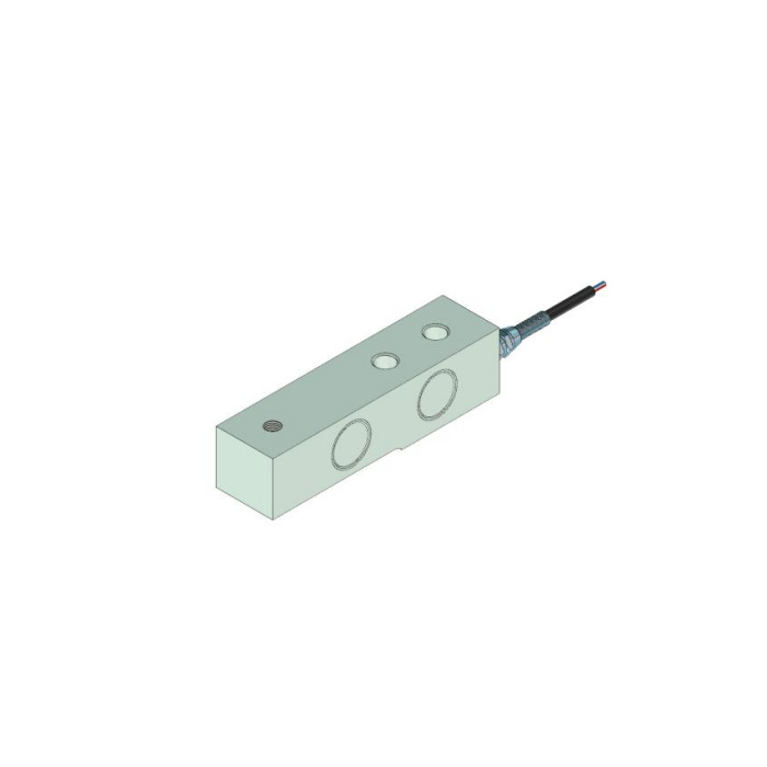

METRAVON MV-LC0045 is a cantilever beam load cell with a smaller load-end opening than the recessed MV-LC0044 reference. Both share a 137 mm length and several fixing dimensions, but their load-transfer parts require separate review. On MV-LC0045, the drawing labels the load-end feature by diameter, not by a metric thread designation. Do not convert a 12 mm opening into an assumed M12 connection when ordering a head or reusing a bracket.
Read the cantilever beam load cell opening as a section, not a thread label
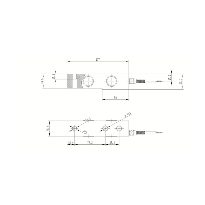
The reference plan carries 12 mm and 13.5 mm diameter callouts at the load end, while the side view has a 17.3 mm vertical annotation beside that feature. Obtain the complete bore, any threaded variant and the mating contact definition for the actual supplied unit. The CAD illustration is not sufficient to settle a thread or engagement. If the installation requires a screwed head, the order needs an explicit thread specification rather than a fitting chosen from the apparent diameter.
Compare the contact with the larger recessed-seat alternative
MV-LC0044 uses a 26/16 mm recessed reference instead of this smaller opening. A retained load head can therefore be unsuitable even if both beams line up with the same fixing holes. Show where the head bears, how it is retained and whether it can bottom on an unintended shoulder. The movable-head description in the family text does not provide a universal head for both versions. Confirm which component is included and keep any permitted contact movement free of guides or guards that can share the reaction.
Retain clearance around the common fixing envelope
The body-length and plan-width references are 137 and 36.6 mm. The end offset is 18.4 mm, followed by 76.2 mm to the first fixing centre and 25.4 mm between the two diameter-13 fixing positions. The section includes 34.5 and 36.6 mm vertical references and a 59 mm lower length. Use the selected rated drawing to define the base support and installed height; matching a top-view pattern does not approve a continuous lower bed, a clamping pocket or every available capacity within the 0-5 t technical entry.
| Item | Value | Selection notes |
|---|---|---|
| Load-end diameter references | 12 / 13.5 mm | No M12 thread or engagement is established by these callouts. |
| Vertical load-end annotation | 17.3 mm | Read it with the complete section and mating contact. |
| Body length / plan width | 137 / 36.6 mm | The required lower support and height still need confirmation. |
| End offset / centre chain | 18.4 / 76.2 / 25.4 mm | Keep the approved load and fixing arrangement with the pattern. |
| Fixing-hole reference | Two 13 mm holes | No fastener torque is inferred from diameter. |
| Documented electrical channel | 2.0 +/-0.002 mV/V | Do not connect the raw bridge to a PLC current input. |
Check useful weight response with the final fitting
Specify dead load, maximum local reaction and the increments that determine a batch or process decision. Reference precision is 0.05% FS, not the same percentage of every small weight reading. Safe load is 150% FS, without establishing impact survival for a dropped product or the strength of a homemade contact pin. After mechanical approval, compare repeat loads and unloading return with the head, restraints and cable installed. A zero shift caused by fitting changes should be investigated before the reader is retared.
Use the documented bridge rather than a guessed digital or current interface
Rated output is 2.0 +/-0.002 mV/V, powered by 10-12 V DC excitation. Input and output resistances are 380 +/-5 and 350 +/-1 ohm respectively, and the cable reference is 6 m. A PLC current input requires an appropriate external weighing conditioner. Confirm delivered wire functions because the signal-colour legend and circuit disagree. Temperature compensation covers -10 to +65 deg C, distinct from -40 to +85 deg C operation. Request the actual IP68 exposure conditions and protect the cable termination accordingly.
Where the support calls for the larger recessed contact, review the MV-LC0044 seat section. Obtain a matched rated drawing and head before deciding whether either reference suits the existing frame.
Diameter callouts, fitting reuse and installed zero
Q1. Does the 12 mm annotation mean that an M12 head will screw in?
No thread is established by a diameter callout. Request the complete delivered connection definition before choosing a threaded fitting. Do not force a screw into an unconfirmed opening or modify the sensor to suit an existing head.
Q2. Can the load head from MV-LC0044 be transferred?
Not without comparing the actual contact sections. The larger 26/16 mm recessed feature of that reference differs from the smaller opening shown here. Check fit, bearing and retention rather than relying on their common 137 mm body length.
Q3. What should be checked after the contact fitting is changed?
Inspect bottoming, unintended shoulder contact, guide restraint and lower support first. Then compare the agreed weights and return after unloading with the final cable restraint. Correcting the empty display alone does not accept the new contact arrangement.
