


 Chinese
 Spanish
 Russian
 Portuguese
 French
 German
 Indonesian
 Thai
 Vietnamese
 Arabic
 Italian
 Turkish
 Polish
 Japanese


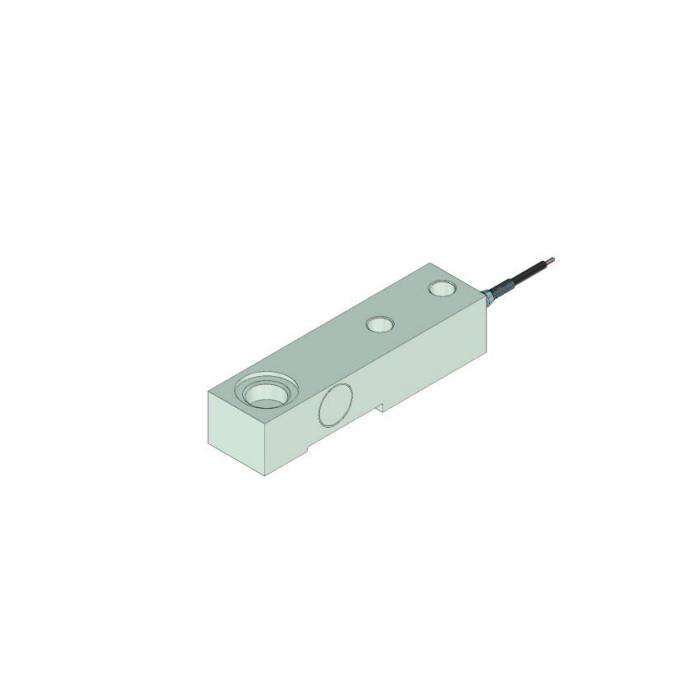

METRAVON MV-LC0046 is a cantilever load cell with a recessed load-end feature and two fixing positions towards the cable end. It is intended for a defined load-head and base arrangement in industrial weighing. The technical table states 0-5 t, while the dimensional table also includes larger ratings. That inconsistency must be resolved for the offered configuration; the presence of a larger dimensional row does not establish a verified higher-capacity product specification.
Match the cantilever load cell fixing group to the selected rating
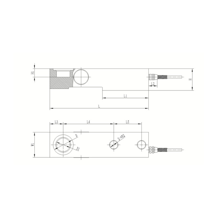
Within the documented technical interval, the 0.5-2 t row gives L203 mm, H43 mm, W1 36.5 mm and D2 fixing holes of 13 mm. The 3 t row retains those body dimensions but changes D2 to 15 mm. The row shared by 5 and 8 t gives L235 mm, H52 mm, W1 47.5 mm and D2 20 mm. Use its 5 t dimensional reference only with confirmation of the offered 5 t assembly. Do not transfer the 8 t designation into the verified technical range.
| Item | Value | Selection notes |
|---|---|---|
| 0.5-2 t: L / H / W1 / D2 | 203 / 43 / 36.5 / 13 mm | Check the complete rated load-end contact as well as the base. |
| 3 t: L / H / W1 / D2 | 203 / 43 / 36.5 / 15 mm | Same outer body does not mean identical fixing-hole size. |
| 5 t reference: L / H / W1 / D2 | 235 / 52 / 47.5 / 20 mm | The shared 5/8 t row does not resolve the technical range discrepancy. |
| Verified technical entry | 0-5 t | Larger dimension rows require separate product confirmation. |
| Bridge sensitivity | 2.0 +/-0.002 mV/V | Use the delivered sensitivity record for calibration. |
| Safe-load entry | 150% FS | Specify support and overload protection independently. |
Keep the recessed load contact separate from the base attachment
The outline distinguishes the load-end D/D1 recess from the two D2 fixing positions. A mating pin, head or seat needs a defined contact and retention arrangement; it is not selected by whichever circular opening appears to fit. Include the underside relief, available height and removal access in the support section. The dimensional table changes the load-end diameters with the mounting group as well. Reusing a loading head therefore requires a contact check in addition to the base-hole comparison.
Confirm reaction and useful weighing interval before retaining a larger group
Provide the permanent structure weight, maximum contents and largest individual reaction under the governing loaded positions. A support that occasionally carries a disproportionate share needs that load case identified. The listed safe-load limit is 150% FS, not a universal design multiplier for the support steelwork. Precision is listed at 0.05% FS, with a separate temperature-effect entry of 0.05% FS per 10 deg C. State the useful weight changes and installed acceptance points rather than assuming those entries determine the result of the complete hopper or platform.
Review the retained indicator against this bridge and cable
The electrical reference gives 2.0 +/-0.002 mV/V sensitivity at 10-12 V DC excitation, with 380 +/-5 ohms input resistance and 350 +/-1 ohm output resistance. Record the other connected cells and any junction-box adjustments if only one support is being changed. The reference cable entry is 6 m. Obtain the delivered terminal record because the circuit and colour list disagree on the signal pair; perform a controlled loading-sign check before adjusting span or corner balance.
Check the actual support after the structure is reassembled
Look for contact at the relieved underside, binding loading parts, changed restraints and cable pull before making zero corrections. Repeat the agreed load positions and unloading return with all normal attachments in place. Temperature compensation is specified for -10 to +65 deg C, distinct from -40 to +85 deg C operation. IP68 also needs the delivered sealing configuration and exposure conditions stated. Neither the wider operating interval nor the enclosure code confirms every immersed pit installation or external cable junction.
Capacity evidence and retained supports
Q1. Does the dimensional table prove a 20 t version is available?
No. The technical specification supplied for this reference stops at 5 t. Obtain a confirmed specification and matching rated drawing before quoting any higher-capacity version; dimensions alone do not establish its electrical or performance limits.
Q2. Can a 3 t cell use the 2 t base without checking it?
The body envelope agrees, but the fixing-hole reference changes from 13 to 15 mm. Review the actual fasteners and supporting contact before retaining the base. A matching overall length is not enough to accept the attachment.
Q3. What should be checked if a replacement sits flat but weighs incorrectly?
Inspect the load-end seat, underside relief, fixed-end attachment and any guides that can share the reaction. Then verify the bridge setup and reference weights. An unloaded zero and a flat-looking base do not establish that the intended force reaches the sensing section.
