


 Chinese
 Spanish
 Russian
 Portuguese
 French
 German
 Indonesian
 Thai
 Vietnamese
 Arabic
 Italian
 Turkish
 Polish
 Japanese


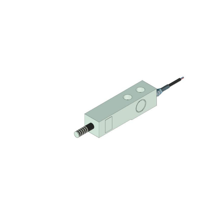

METRAVON MV-LC0047 is a cantilever load cell whose M14 x 2 stud projects from the end opposite the cable. This differs mechanically from a beam loaded through a vertical hole or recess. The reference describes weighing applications but does not establish a general-purpose axial tension or compression specification for the stud. Selection should show where the applied force acts, how the beam is fixed and what the stud connects to in the complete weighing arrangement.
Show the installed force direction before choosing the axial-stud load cell
An end stud is a connection feature, not proof that force should be applied along its axis. Submit the mating bracket, force arrow and supporting faces in section. Identify any offset between the reaction and the approved loading position. Ask for a rated assembly drawing that confirms the intended direction and contact parts. Do not use this model as an inline tension cell merely because the thread can accept a coupling; the available description does not supply that loading approval or a bidirectional calibration.
Fit the M14 x 2 connection without imposing assembly strain
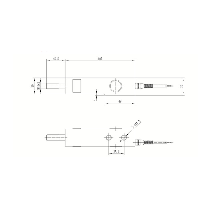
The body-length reference is 107 mm with a further 45.5 mm end projection reference. The outline marks M14 x 2 explicitly. Confirm usable threaded engagement, the unthreaded shoulder and the method of holding the assembly during tightening. The projection is not an engagement specification or a length of fully usable thread. A fitting that bottoms on the wrong surface can preload the beam before a process load is applied. No tightening torque or anti-rotation hardware is defined in the reference.
Preserve the stepped support and two-hole fixing arrangement
Two diameter-11.5 fixing holes are shown 25.4 mm apart. The side view includes a 4 mm underside step, a 49 mm lower reference and vertical annotations of 36 and 32 mm. Review which supporting face is intended to contact the base. A packing strip across the entire underside can eliminate a required clearance. Also reserve space for the cable gland and free lead at the opposite end; neither the body length nor the end projection includes every installed cable bend or tool-access allowance.
| Item | Value | Selection notes |
|---|---|---|
| End connection | M14 x 2 | Confirm engagement, holding method and approved loading direction. |
| Body / end projection references | 107 / 45.5 mm | The visible projection is not all usable thread. |
| Fixing holes / centre spacing | Two 11.5 mm holes / 25.4 mm | Match the selected rated supporting arrangement. |
| Underside step / lower reference | 4 / 49 mm | Do not fill the clearance with an unapproved continuous spacer. |
| Vertical references | 36 / 32 mm | Resolve the contact planes with the complete support section. |
| Signal / safe load | 2.0 +/-0.002 mV/V / 150% FS | Neither value establishes an inline tensile rating. |
Establish the mechanical zero before setting the weighing channel
After the approved connection is fitted, check unloaded return and reference readings with the final cable restraint. If tightening the coupling changes zero, inspect bottoming, constrained movement and fixture contact before applying an electronic tare. The bridge uses 10-12 V DC excitation and nominal 2 mV/V output, with sensitivity tolerance +/-0.002 mV/V. Its input and output resistances are 380 +/-5 and 350 +/-1 ohms. Delivered wire functions must resolve the disagreement between the reference circuit and signal-colour list.
Specify duty and exposure without assuming stud strength from sensor capacity
The technical entry is 0-5 t and requires a definite offered rating. Precision is 0.05% FS, temperature effect 0.05% FS per 10 deg C and safe load 150% FS. None of those entries supplies a separate tensile strength or bending allowance for the proposed coupling. The compensated interval is -10 to +65 deg C; the wider operating interval is -40 to +85 deg C. For the IP68 entry, define the expected exposure and termination. A sealed sensing body does not approve an arbitrary external joint or cable connection.
Where the required head connects vertically, compare the MV-LC0051 M16 load-end layout. Its stepped body and vertical opening differ from this axial-stud arrangement, so the comparison does not establish interchangeability.
Stud direction, engagement and assembly preload
Q1. Can the stud be pulled axially as an inline tension sensor?
That use is not established by the weighing-beam reference. Request an explicitly approved force direction and corresponding calibration before designing the coupling. A threaded connection alone does not demonstrate axial or reversed-load suitability.
Q2. Is 45.5 mm the threaded engagement available to the coupling?
It is an end projection reference. Confirm the actual thread length, shoulder and permitted engagement on the released drawing. Do not let a coupling bottom against an unintended surface to consume the full projection.
Q3. Why might the unloaded reading move when the end fitting is tightened?
The joint may be imposing preload or restraint through bottoming or an incorrect support face. Inspect the mechanical assembly before changing zero. Then repeat the intended weight references with the final locking and cable arrangements.
