


 Chinese
 Spanish
 Russian
 Portuguese
 French
 German
 Indonesian
 Thai
 Vietnamese
 Arabic
 Italian
 Turkish
 Polish
 Japanese



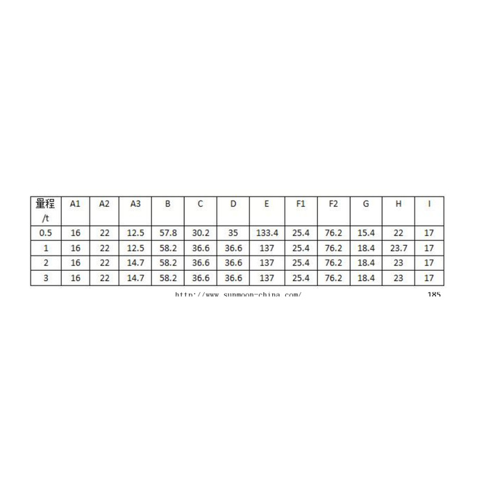
METRAVON MV-LC0048 is a compact beam load cell with a recessed load-end opening and capacity-dependent installation details. The dimensional table lists 0.5, 1, 2 and 3 t rows, while the technical range is written as 0-5 t. In particular, the 1 t and 2 t rows share several outside dimensions but differ in their fixing-hole and recess entries. Compare the complete rated row before reusing the base, loading pin or contact fitting.
Read the compact beam load cell table together with its section
For 0.5 t, the table gives body length E133.4 mm, plan width C30.2 mm and height D35 mm. At 1, 2 and 3 t, E is 137 mm and C/D are both 36.6 mm. The fixed-end F1 spacing remains 25.4 mm, with F2 at 76.2 mm across all listed rows. These shared spacings do not erase the different body and contact features. Keep the table letter labels attached to the reference sketch instead of replacing them with assumed equivalents from another beam.
Check the A3 and H differences when retaining a base or load fitting
A3 is listed as 12.5 mm at 0.5 and 1 t, then 14.7 mm at 2 and 3 t. The recessed-section H reference is 22 mm for 0.5 t, 23.7 mm for 1 t and 23 mm for 2/3 t. The section shows that the load opening has more than one diameter and a defined depth. Obtain the detailed contact and fixing definitions before choosing a pin, screw or shoulder. A model suffix is not evidence of a metric thread, a current output or a particular mating component.
| Item | Value | Selection notes |
|---|---|---|
| 0.5 t: E / C / D | 133.4 / 30.2 / 35 mm | A3 is 12.5 mm and H is 22 mm in this row. |
| 1 t: E / C / D | 137 / 36.6 / 36.6 mm | A3 is 12.5 mm; H changes to 23.7 mm. |
| 2 / 3 t: E / C / D | 137 / 36.6 / 36.6 mm | A3 is 14.7 mm and H is 23 mm. |
| F1 / F2 spacing references | 25.4 / 76.2 mm | Retain the complete selected row despite common spacings. |
| Technical / dimensional coverage | 0-5 t / 0.5, 1, 2, 3 t rows | An unlisted capacity needs its own installation drawing. |
| Safe-load entry | 150% FS | No loading-pin or fixture capacity is inferred from this limit. |
Resolve the missing rated rows before quoting the requested capacity
The 0-5 t technical entry does not supply a 5 t installation outline. If the project needs a rating not represented in the dimensional rows, request its own approved drawing and configuration. Include available height, fixed-end contact, head travel and removal access. Do not scale the 3 t drawing or declare the 137 mm envelope universal. The quotation should distinguish the sensing beam from the load fitting and any restraint or overload-stop parts.
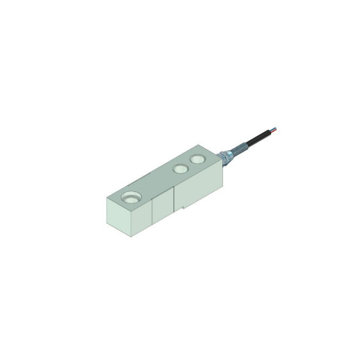
Match a restricted installation to a useful weight interval
Provide permanent dead load, maximum local reaction and the weight increments used for process acceptance. The precision entry is 0.05% FS; this does not demonstrate the installed result for a small increment on a larger rated beam. Supply the expected sensor temperature as well: compensation is listed over -10 to +65 deg C, while operation extends to -40 to +85 deg C. The 0.05% FS per 10 deg C temperature entry should be reviewed with that distinction rather than used as a whole-system error budget.
Confirm the bridge and recheck the final load-end contact
This is an analogue bridge reference: 2.0 +/-0.002 mV/V sensitivity, 10-12 V DC excitation, 380 +/-5 ohms input and 350 +/-1 ohm output resistance. Cable length is listed as 6 m. Obtain the supplied connection record instead of selecting polarity from the conflicting colour list and circuit. Check reference weights and unloaded return after the final recessed fitting and cable restraint are installed. The IP68 entry needs agreed exposure conditions, and the 150% FS safe-load limit does not define the strength of an improvised pin or the commissioning load for a complete support.
Shared envelopes and different recessed details
Q1. Can the 1 t base and load fitting be reused for a 2 t unit?
Their E, C and D references agree, but A3 changes from 12.5 to 14.7 mm and H from 23.7 to 23 mm. Review the matched fixing and recessed contact details rather than accepting the shared external envelope.
Q2. Does the M suffix identify the electrical interface?
The documented output here is mV/V. The suffix alone establishes neither a 4-20 mA version nor a particular thread. Use the explicit electrical specification and drawing, with the actual offered configuration identified.
Q3. Which outline should be used for a 5 t order?
Request a confirmed 5 t drawing. The available metric table stops at 3 t although the technical range extends to 5 t. Do not enlarge an earlier drawing or reuse its hole and recess values without confirmation.
