


 Chinese
 Spanish
 Russian
 Portuguese
 French
 German
 Indonesian
 Thai
 Vietnamese
 Arabic
 Italian
 Turkish
 Polish
 Japanese


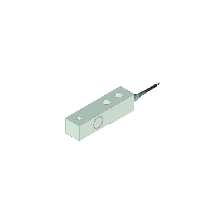

METRAVON MV-LC0049 is a cantilever beam load cell whose fixing features include paired recessed openings at the cable end. The available outline is 130 mm long and identifies a separate load-end opening. Those features need different mating parts and functions. For a low-profile frame, check both fastener-head clearance and the force contact; a beam that physically fits beneath the structure can still be restrained or loaded incorrectly.
Check the counterbored fixings without assuming screw size or length
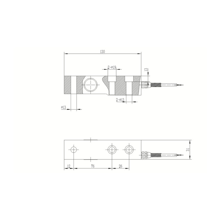
The reference section calls out two diameter-19 recesses above two diameter-13 openings, with a 13 mm vertical recess reference. The plan gives a 26 mm centre spacing for the paired fixing positions. Confirm the fastener head, washers if required, mating-plate thickness and permitted engagement against the selected assembly. Hole diameter does not specify fastening torque. A screw head or washer contacting a recess shoulder incorrectly can change how the fixed end is seated even before the scale carries material.
| Item | Value | Selection notes |
|---|---|---|
| Body length / plan width | 130 / 31 mm | Check underside relief and fixed-end contact separately. |
| Paired fixing features | 19 mm recess / 13 mm opening | The recess vertical reference is 13 mm. |
| Fixing centre spacing | 26 mm | Match the actual fasteners and base contact, not just hole diameter. |
| Load-end opening | 13 mm diameter reference | This is not an M13 thread annotation. |
| Load-end offset / next spacing | 12 / 76 mm | Use the complete force-contact and fixation arrangement. |
| Bridge input / output | 380 / 350 ohms | Input tolerance is +/-5 and output tolerance +/-1 ohm. |
Separate the cantilever beam load cell contact from its fixing positions
The load end is shown with a diameter-13 opening, a 12 mm end offset and 76 mm spacing to the nearer fixing centre. The plan-width reference is 31 mm and overall body length 130 mm. No thread is identified at that load-end opening. Obtain the approved pin, head or other contact detail rather than treating it as an M13 attachment. Show the direction of the intended reaction and any part that retains or guides the moving structure.
Leave the underside relief and cable end free of unwanted contacts
The section includes a relieved lower portion. A continuous bed, packing strip or guard that reaches into that region can become another support as force is applied. Submit a section through the real base and load fitting, not only a top-view hole pattern. Reserve cable exit and removal space at the fixed end. The reference lists 6 m of cable, but that length does not define a permissible tight bend or establish that a longer extension may be added without checking the measurement channel.
Choose the rated version and verify the actual weighing channel
The technical range is written as 0-5 t, with no capacity-specific series of outline rows on this sheet. Request the selected rated drawing and sensitivity record. Bridge output is 2.0 +/-0.002 mV/V at 10-12 V DC excitation, with 380 +/-5 ohms input and 350 +/-1 ohm output resistance. Use delivered terminal identification to resolve the inconsistent reference colour and circuit polarity. Compare reference weights after the final fixings, head and cable route are complete; an electrical zero adjustment is not a substitute for seating the fixed end correctly.
Keep the published limits separate from whole-frame acceptance
Precision is listed at 0.05% FS, with temperature effect 0.05% FS per 10 deg C and compensation from -10 to +65 deg C. The operating-temperature entry extends from -40 to +85 deg C, without establishing equal measurement performance over that wider interval. Safe load is 150% FS and protection is IP68 subject to the actual exposure conditions. Define the useful weight range, load positions and allowable installed readings independently. The beam specification does not supply impact performance for the attached frame or a strength rating for an unconfirmed contact fitting.
Fixing recesses and load-end openings
Q1. Can the 13 mm load-end opening take an M13 fitting?
A diameter callout is not a thread specification. Obtain the approved load-transfer component and retaining arrangement before ordering a fitting. Do not cut a new thread into the sensor to make a bracket fit.
Q2. Do the recessed fixings allow the entire body to lie on a flat bed?
Not from the recess detail alone. The underside relief and intended fixed-end support still need to remain as defined by the approved assembly. A bed extending into the active region can create an unintended force path.
Q3. What needs inspection if calibration changes after the screws are retightened?
Check seating, fastener-head contact and whether the load head or lower relief touches adjacent structure. Recheck reference weights with the accepted fastening arrangement. Merely correcting zero cannot establish that the installed span is unchanged.
