


 Chinese
 Spanish
 Russian
 Portuguese
 French
 German
 Indonesian
 Thai
 Vietnamese
 Arabic
 Italian
 Turkish
 Polish
 Japanese



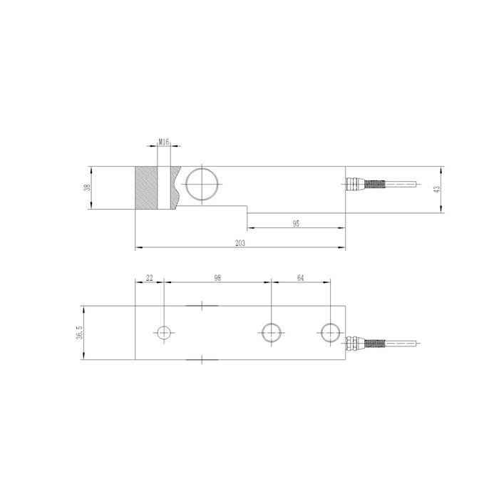
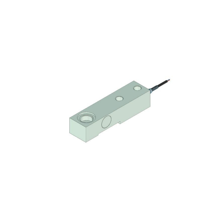
METRAVON MV-LC0050 is a cantilever beam load cell with a published 0-5 t range and a nominal 2 mV/V output. It is a candidate for low-profile platform and hopper weighing where the frame can accommodate its mounting and load-introduction arrangement. Check the largest reaction at each support, not only the total scale load divided by the number of sensors.
MV-LC0050 electrical and environmental specifications
| Parameter | Published value |
|---|---|
| Nominal load range | 0-5 t |
| Rated output | 2.0 +/-0.002 mV/V |
| Excitation | 10-12 V DC |
| Input resistance | 380 +/-5 ohm |
| Output resistance | 350 +/-1 ohm |
| Published accuracy figure | 0.05% of full scale |
| Compensated temperature range | -10 to +65 deg C |
| Operating temperature range | -40 to +85 deg C |
| Protection rating | IP68 |
| Listed cable length | 6 m |
| Safe load limit | 150% of full scale |
The accuracy entry describes the sensor under its specified test conditions, not the completed scale's error. Also distinguish the operating and compensated temperature ranges. An installation within the operating range still needs its temperature-related measurement error assessed when it lies outside the compensation range.
Keep the mounting and loading points distinct
The catalogue drawing shows a 203 mm overall length. Use that as an initial fit check, then obtain the approved drawing for the selected capacity to verify hole centres, loading hardware and clearances. The base must support the intended mounting area without blocking the beam's measuring deflection.
A load introduced off the intended contact position can change the sensor response. Check the platform or hopper support arrangement for sideways restraint, binding and contact with surrounding structures. Do not use electrical corner adjustment to conceal a mechanical load path that changes as the scale is filled. Keep normal operation within the selected rated capacity; the 150% safe load limit does not extend the calibrated weighing range.
Connect the bridge to a suitable weighing input
| Catalogue lead colour | Connection |
|---|---|
| Red | Positive excitation |
| Blue | Negative excitation |
| White | Positive signal |
| Yellow | Negative signal |
Verify these assignments against the delivered sensor's documentation, particularly on a repaired cable. Match the instrument's bridge excitation, millivolt input range and allowable bridge load. A general PLC voltage or current input is not a substitute for a compatible load-cell input.
For several cells feeding one indicator, use the junction-box wiring and adjustment guide to plan the connection and corner checks. Record the unloaded reading, known-load response at each position and return to zero after installation.
Platform-scale questions
Q1. Can four sensors be selected using one quarter of the total weight?
Only as an initial estimate for an evenly loaded structure. The design must account for the scale's own weight, the worst load position and applicable dynamic forces at each support. A wheel or concentrated load near one corner can create a much larger local reaction than the average.
Q2. Does IP68 make every washdown or chemical exposure acceptable?
No. Confirm the enclosure test conditions, cable termination and selected material against the actual cleaning process. The material listing allows alloy steel or stainless steel; identify the supplied version rather than assuming the IP rating establishes its chemical resistance.
Enquire about MV-LC0050 with the support layout, maximum support reaction, mounting dimensions, indicator model and cable route. Include the required material and exposure conditions so that the quotation identifies a usable sensor configuration rather than just a load rating.
