


 Chinese
 Spanish
 Russian
 Portuguese
 French
 German
 Indonesian
 Thai
 Vietnamese
 Arabic
 Italian
 Turkish
 Polish
 Japanese



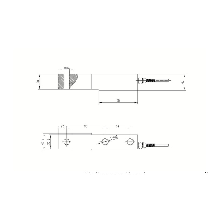
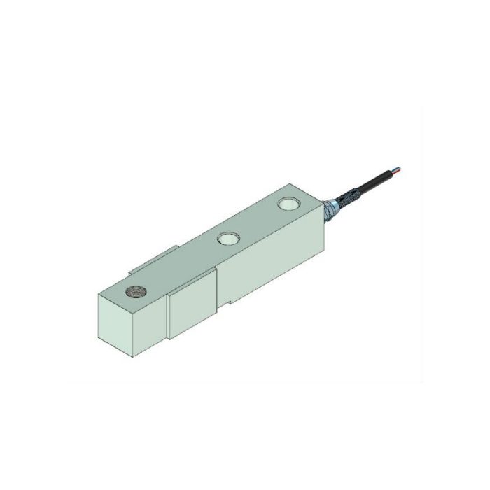
METRAVON MV-LC0051 is a beam load cell with an M16 load-end annotation and a stepped body in its reference outline. The threaded opening is vertical, unlike the axial end stud of MV-LC0047. For a replacement, the mating load head, supporting footprint and changes in section matter as much as nominal signal sensitivity. The available 0-5 t technical entry does not prove that every offered rating has this same physical assembly.
Confirm the M16 load-end beam load cell connection in section
The outline marks M16 at the load end but does not state a pitch or permitted engagement. Request the full thread designation, usable depth and matched head drawing for the selected rated unit. Check whether the head bears on an approved contact or can bottom against an unintended shoulder. A threaded opening should not be used to add a rigid brace that restrains the beam. The reference provides no tightening torque, tensile calibration or approved reversed-loading duty for the proposed fitting.
Review both widths and heights before machining a pocket
The side view shows 38 and 43 mm height references, while the plan identifies 43.5 mm at the wider end and 36.5 mm through the narrower body. A base or guard designed around only the narrower section may touch the wide end or its transition. Conversely, a continuous support designed to fill every underside gap can restrain the active region. Show all intended contact faces and clearances in a section through the base, beam and top structure rather than enclosing the whole outline in a tight pocket.
| Item | Value | Selection notes |
|---|---|---|
| Load-end thread annotation | M16 | Full pitch, engagement and mating head require confirmation. |
| Vertical section references | 38 / 43 mm | Identify the actual bearing faces on the rated assembly drawing. |
| Wider end / narrower body | 43.5 / 36.5 mm | Check side and guard clearance at the transition. |
| Centre-position chain | 22 / 98 / 64 mm | Not a complete overall body length. |
| Cable-end lower reference | 95 mm | Its support function must follow the confirmed assembly. |
| Sensitivity / safe-load entry | 2.0 +/-0.002 mV/V / 150% FS | No tensile or attachment-strength approval is inferred. |
Keep the fixing chain and support-length reference distinct
The plan gives a 22 mm end offset followed by 98 and 64 mm centre spacings. The side view separately marks 95 mm towards the cable-end portion. These references locate different features and are not a complete end-to-end length specification. Obtain the full rated drawing, including the fixing-hole diameters and any tolerances, before fabricating the base. Do not derive missing external length by adding only the centre chain or assigning a supporting purpose to the 95 mm feature without the assembly detail.
Specify the dead load and load-head movement the beam will see
For a hopper or low platform, provide empty structure weight, maximum contents and the reaction at the most heavily loaded support. Include pipe restraints or guides that might oppose the movement of the threaded head. The 150% FS safe-load entry describes the sensor limit rather than a design load for that head and its surrounding hardware. Precision is listed at 0.05% FS; agreement is still needed on useful weight increments and repeat-load acceptance with the actual installed contact.
Read and calibrate the bridge after the head and base are accepted
The signal reference is 2.0 +/-0.002 mV/V with 10-12 V DC excitation. Input resistance is 380 +/-5 ohms and output resistance is 350 +/-1 ohm; cable length is listed as 6 m. Confirm the terminal functions from the supplied record instead of following contradictory signal-colour references. Compare loading and unloading readings with the final head, restraints and cable secured. Temperature compensation covers -10 to +65 deg C, operation -40 to +85 deg C, and temperature effect is 0.05% FS per 10 deg C. For IP68, obtain the actual exposure conditions rather than assuming the external head or cable junction is equally protected.
For an end-projecting attachment, the MV-LC0047 M14 x 2 stud arrangement shows a different connection direction. Confirm the actual force and fixing scheme rather than rotating one beam drawing to stand in for the other.
Thread orientation and stepped clearances
Q1. Is the M16 feature an axial stud like MV-LC0047?
No. This reference shows a vertical threaded opening, while MV-LC0047 has an axial M14 x 2 end stud. Their mating arrangements and force introduction need separate drawings. Shared nominal mV/V output cannot establish a mechanical substitution.
Q2. Can the M16 pitch be taken from a standard fitting already in stock?
Not without confirming the complete thread on the delivered drawing. The available annotation supplies only M16. Obtain pitch, usable engagement and the head contact requirements before reusing a fitting.
Q3. Does the centre-position chain give the complete body length?
It does not include every end clearance or external feature. Request the full rated outline and cable envelope before setting a pocket or guard length. Do not manufacture the base from a sum of centre spacings alone.
