


 Chinese
 Spanish
 Russian
 Portuguese
 French
 German
 Indonesian
 Thai
 Vietnamese
 Arabic
 Italian
 Turkish
 Polish
 Japanese


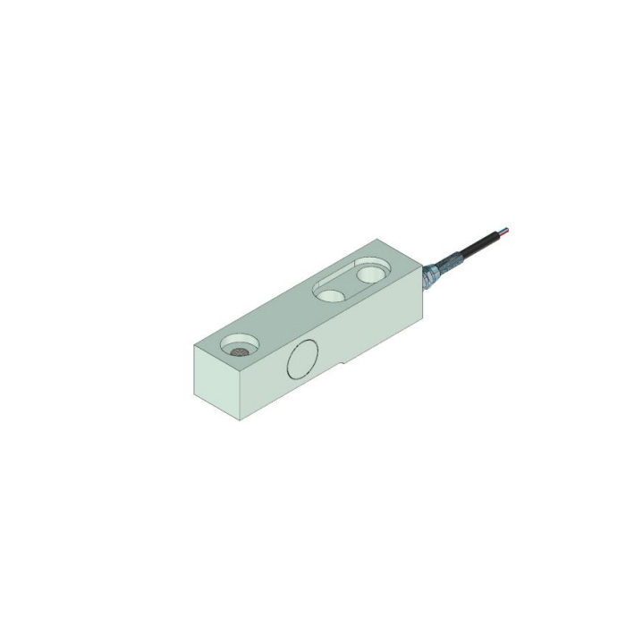

METRAVON MV-LC0052 is a cantilever load cell with recessed mounting features in its reference outline. It can be considered for low-platform or hopper supports when the beam, load-end contact and fixing arrangement are reviewed together. The technical range is written as 0-5 t; that does not identify the discrete rated capacities available for purchase. State the required rating and obtain its matched drawing rather than treating a measuring interval starting at zero as a list of supplied versions.
Check the cantilever load cell recesses before choosing the fasteners
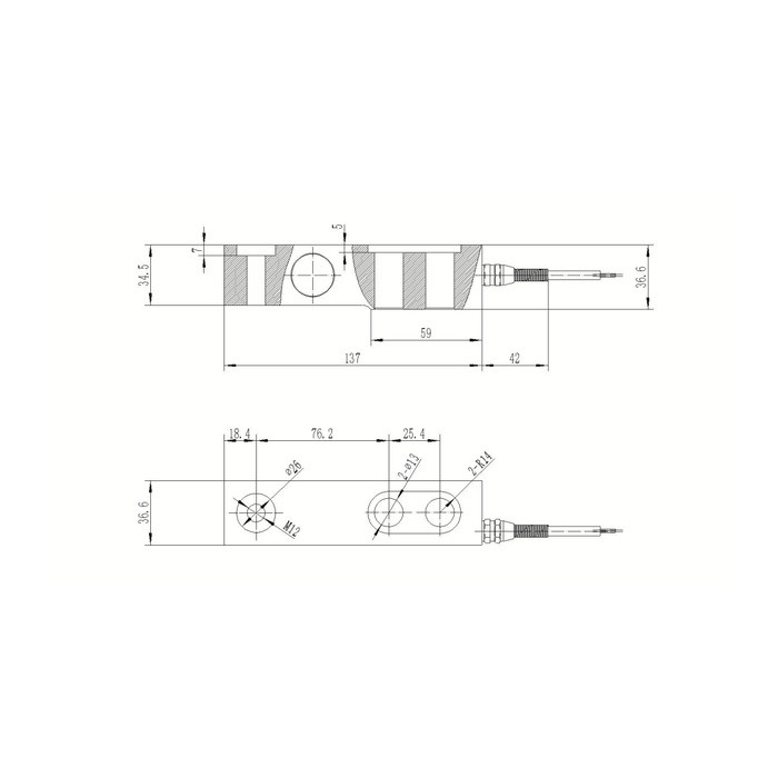
The drawing gives a 137 mm body-length reference and a further 42 mm cable-exit reference. In plan it shows an 18.4 mm end offset followed by 76.2 and 25.4 mm hole-centre spacings. The two fixing positions have separate clearance-hole and recess annotations. Confirm their diameters and the fastener-head fit on the supplied rated drawing; the opposite end has an M12 annotation and a diameter-26 recess reference. Match the fastener heads, bearing surfaces and mating load part to the complete section. A recessed opening is not permission to fit any screw that passes through its smallest diameter.
Resolve the support height and load contact on the rated drawing
The plan-width reference is 36.6 mm, and the section includes separate 34.5 and 36.6 mm vertical annotations. Confirm which contact planes define the installed height for the offered assembly. Include the base plate, load fitting and any washers in that review. Keep the active section free of a continuous support or a cover that can take part of the reaction. The reference illustration shows the beam shape but does not define a complete anti-lift or lateral-restraint system for a vessel.
Use the compensated temperature interval for the measurement review
The stated temperature-compensation interval is -10 to +65 deg C, within a wider operating range of -40 to +85 deg C. Operation within the wider interval does not establish unchanged weighing error outside the compensated interval. For the selected rating, the 0.05% FS precision entry uses full scale as its basis; the separate temperature-effect entry is 0.05% FS per 10 deg C. Provide the expected sensor temperature, useful weighing interval and required reference checks. A 150% FS safe-load limit is also listed. Do not substitute the 200% figure of a different beam model or treat the safe-load limit as a routine commissioning load.
| Item | Value | Selection notes |
|---|---|---|
| Technical range entry | 0-5 t | Request a specific rated capacity, not an assumed continuous supply range. |
| Body / cable-exit references | 137 / 42 mm | Free cable bend and tool access require additional space. |
| Hole-centre chain | 18.4 / 76.2 / 25.4 mm | Confirm the full section and recessed fastening arrangement. |
| Bridge input / output resistance | 380 / 350 ohms | Listed tolerances are +/-5 and +/-1 ohm respectively. |
| Compensated / operating temperature | -10 to +65 / -40 to +85 deg C | Do not equate operating survival with the compensated measurement interval. |
| Safe load / cable entry | 150% FS / 6 m | Confirm the actual cable and overload protection for the installation. |
Specify the reader, cable and installed checks as one channel
Sensitivity is 2.0 +/-0.002 mV/V with 10-12 V DC excitation. The resistance entries are 380 +/-5 ohms input and 350 +/-1 ohm output, so the reader review should use these values rather than the common 400/350-ohm pair. The reference lists 6 m of cable and IP68 protection, but the actual cable assembly and immersion conditions belong in the offer. Obtain the delivered terminal functions because the reference colour list and circuit disagree. Accept the support with agreed load points and unloading return after the final head, restraints and cable are installed.
Recessed bases and temperature limits
Q1. Does the 0-5 t entry mean any rated capacity can be ordered?
It describes the technical range, not every purchasable rating. Ask the quotation to identify the selected rated capacity, sensitivity record and matching mechanical configuration. A required lower rating needs its own confirmation.
Q2. Can the unit be used at -30 deg C with the same error requirement?
The operating entry includes that temperature, but the stated compensation interval does not. Submit the actual temperature and required weighing result for confirmation. Do not extend the compensated performance assumption from -10 deg C to the full operating range.
Q3. What should be supplied with a recessed-base replacement enquiry?
Provide the base section, fixing-head dimensions, load-end fitting and installed height, plus support reaction and reader details. Include the cable route and exposure. Those details determine whether the new beam and retained hardware form a usable assembly.
