


 Chinese
 Spanish
 Russian
 Portuguese
 French
 German
 Indonesian
 Thai
 Vietnamese
 Arabic
 Italian
 Turkish
 Polish
 Japanese



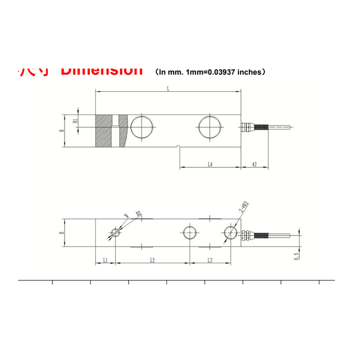
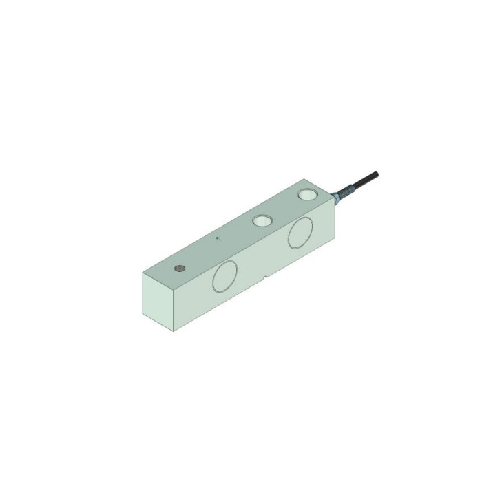
METRAVON MV-LC0053 is a cantilever beam load cell for load-head arrangements in low platforms and hoppers. Its 0.5-5 t family is divided into two dimensional groups. Upgrading from the smaller group to 3-5 t changes length, fixing positions, section size and the load-end thread. Check those changes before retaining a base plate or ordering a replacement head; the family name and common mV/V signal do not establish a mechanical fit.
Compare both cantilever beam load cell mounting groups
For 0.5-2 t, the metric table gives L130 mm, H/B31.8 mm and L2 76.2 mm. The two D3 fixing holes are 13 mm and the D2 connection is marked M12. For 3-5 t, L becomes 171.5 mm, H/B38.1 mm and L2 95.3 mm; fixing holes become 20 mm and the connection is M18 x 1.5. The end offset and fixing spacing also change. Review the complete rated outline instead of adding a spacer or moving one hole to make the old assembly appear to fit.
| Item | Value | Selection notes |
|---|---|---|
| 0.5-2 t L / H-B / L2 | 130 / 31.8 / 76.2 mm | Fixing D3 is 13 mm; D2 connection is marked M12. |
| 3-5 t L / H-B / L2 | 171.5 / 38.1 / 95.3 mm | Fixing D3 is 20 mm; D2 connection is M18 x 1.5. |
| Lower / upper fixing spacing L3 | 25.4 / 38.1 mm | Use the full hole pattern with the corresponding rating. |
| Sensitivity | 2.0 +/-0.002 mV/V | Confirm the delivered calibration before retaining span settings. |
| Safe-load entry | 150% FS | Not a routine installed-scale test requirement. |
| Compensation / cable reference | -10 to +65 deg C / 6 m | Confirm the actual exposure, cable assembly and termination. |
Keep connection size, engagement and supplied head distinct
The M12 entry does not state a pitch. Obtain the full connection specification for the smaller group and the usable engagement for either group. Identify whether the quote includes a head, seat, fasteners or only the sensor. The document description of a movable head does not define its complete supply or retention arrangement. If an old head will be reused, include its section and contact condition. A worn or binding interface can change the loading response even when the thread can be assembled.
Treat the 150% safe-load entry as a limit, not a project test
This model lists 150% FS safe load with 0.05% FS precision. The temperature-effect entry is 0.05% FS per 10 deg C, and the compensation interval is -10 to +65 deg C. These figures differ from some visually similar beams. Define maximum support reaction, foreseeable shock and mechanical overload protection independently. Use an agreed verification load and method within the accepted installation limits rather than applying the safe-load percentage to the whole hopper or platform as a commissioning instruction.
Check the six-metre cable and bridge with the actual reader
The reference cable length is 6 m. Rated sensitivity is 2.0 +/-0.002 mV/V, input resistance 380 +/-5 ohms and output resistance 350 +/-1 ohm, with 10-12 V DC excitation. Confirm delivered cable length and termination, particularly if replacing only one cell in a connected weighing network. Use the unit connection record to resolve the contradictory signal-colour references. The IP68 entry does not supply an unlimited immersion depth or duration, so specify the exposure and junction-box position before the offer is accepted.
Inspect the final support before calibrating the process
Confirm that pipes, guides, lift restraints and cable supports do not carry part of the intended vertical reaction. Then compare the agreed loading and unloading points with the final hardware fitted. A zero adjustment cannot demonstrate correct load transfer through a binding head. Include the empty vessel or platform, normal operating loads and any permitted movement in acceptance. The wider -40 to +85 deg C operating range is separate from the compensated measurement interval and should not be used to promise the same installed error at every temperature.
Group changes, enclosure exposure and acceptance
Q1. What changes when a 2 t cell is replaced with a 3 t cell?
The order crosses the dimensional-group boundary. Body length and section, fixing-hole sizes, spacings and the load-end connection change. Recheck the base and contact parts rather than treating the new rating as an electrical scaling change.
Q2. Can IP68 be specified without giving the immersion conditions?
State the expected depth, duration, medium and cable termination in the enquiry. The code alone does not identify every exposure condition accepted for the delivered assembly. Keep the junction box and reader protection in that review.
Q3. Should the maximum working load be multiplied by 150% for acceptance?
Not from the safe-load entry alone. Define an approved acceptance procedure for the complete structure and measurement range. The sensor limit is not evidence that retained heads, supports or vessel hardware can be tested at that load.
