


 Chinese
 Spanish
 Russian
 Portuguese
 French
 German
 Indonesian
 Thai
 Vietnamese
 Arabic
 Italian
 Turkish
 Polish
 Japanese


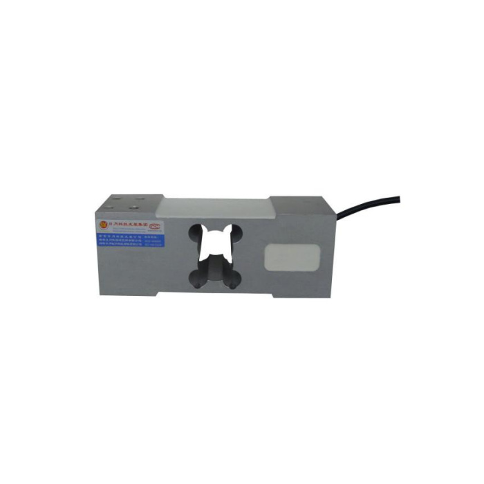

METRAVON MV-LC0054 is a single-point platform load cell with an open parallel-beam sensing section and a 50-800 kg technical range. Its outline provides attachment views on different planes of the body. A replacement decision therefore needs the tray and base drawings, not just the outside dimensions. The reference describes corner adjustment within a specified loading plane, but it does not give a maximum tray size for every rated version.
Identify both attachment planes on the single-point platform load cell
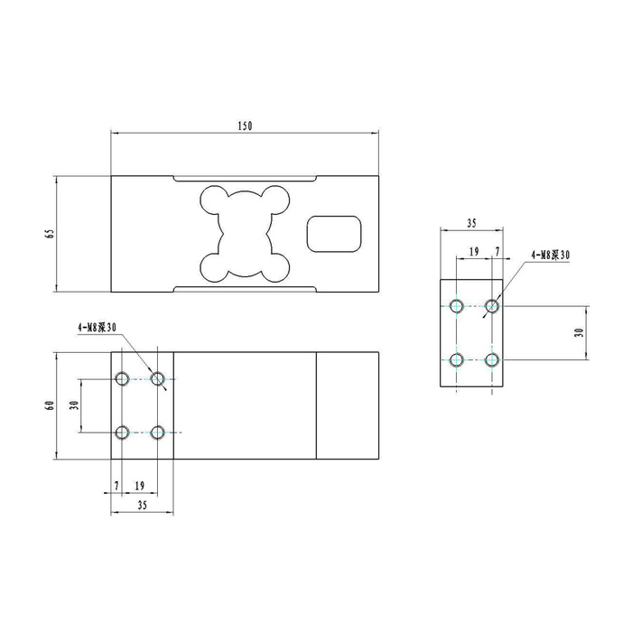
The body reference is 150 mm long, with 65 mm in the side view and 60 mm in the plan view. Attachment details show four M8 positions with a 30 mm depth annotation and a 19 by 30 mm centre pattern. The drawing presents those patterns on separate views. Confirm which face supports the base and which attaches to the platform before transferring holes to a fabrication drawing. The depth annotation is not a recommendation to use a 30 mm-long screw without checking plate thickness, engagement and bottoming clearance.
| Item | Value | Selection notes |
|---|---|---|
| Technical family | 50-800 kg | Request the offered rating and permitted platform arrangement. |
| Body length / side / plan references | 150 / 65 / 60 mm | Map the attachment faces using all views, not one silhouette. |
| Attachment annotation | Four M8 positions, 30 mm depth | Verify the full threaded-hole specification and screw engagement. |
| Attachment centre pattern | 19 x 30 mm | Check the pattern on each intended attachment face. |
| Bridge excitation / sensitivity | 10-12 V DC / 2.0 +/-0.001 mV/V | A current-input controller needs suitable signal conditioning. |
| Input / output resistance | 400 / 350 ohms | Tolerances are +/-20 and +/-5 ohms respectively. |
Review tray stiffness without restraining the open sensing section
The central opening and relieved faces must retain their intended freedom of movement. A wraparound bracket, rigid guard or second support touching this section can divert the measured load. Send a section through the tray, both attachments and the surrounding housing. Include the tray dead weight, extreme permitted load positions and normal handling. Corner adjustment in the sensor description does not compensate for a tray rubbing on a cover or a bracket carrying force outside the intended attachment faces.
Select the bridge reader before considering a current-output alternative
MV-LC0054 specifies 2.0 +/-0.001 mV/V output, 10-12 V DC excitation and a 400 +/-20 ohm input with a 350 +/-5 ohm output resistance. It requires a weighing bridge reader or an appropriate conditioner. A PLC current input cannot read the bare bridge directly. Confirm the delivered terminal identification; the colour list and circuit do not agree on signal polarity. Keep the actual channel and its calibration in the quote rather than assuming that all members of this platform family use the same electrical interface.
Accept the platform over the positions the operator will use
Use agreed reference weights at the centre and specified edge or corner positions, followed by unloading-return and repeat-load checks. Inspect attachments and housing clearances before correcting an uneven position response in the instrument. The specification entries are 0.05% FS precision, 0.02% FS per 10 deg C temperature effect and -40 to +85 deg C operation; they do not supply a finished-scale corner-error limit. IP67 and a 200% FS safe-load entry do not establish resistance to every cleaning fluid or to a dropped load striking an unsupported tray edge.
For a current-input control system, compare the MV-LC0055 current-output reference. Its longer covered body, 12-24 V supply entry and unconfirmed current-circuit details make it a separate mechanical and electrical selection.
Attachment faces and platform position checks
Q1. Can both ends be attached to the same continuous base?
That is not established by the separate attachment views. The fixed and platform-connected faces must follow the approved arrangement so load passes through the sensing section. Submit the complete tray/base section before deciding the mounting orientation.
Q2. Is the M8 depth the screw length to order?
No. Required screw length also depends on the attached plate and the permitted engagement. Check the actual hole depth and bottoming clearance on the released drawing. No fastening torque is supplied by the M8 annotation alone.
Q3. What needs checking if only the centre weight is correct?
Repeat the specified off-centre positions with the same reference weight and inspect tray rigidity, housing contact and both attachments. A correct centre span cannot rule out a constrained sensing section or an oversized platform.
