


 Chinese
 Spanish
 Russian
 Portuguese
 French
 German
 Indonesian
 Thai
 Vietnamese
 Arabic
 Italian
 Turkish
 Polish
 Japanese


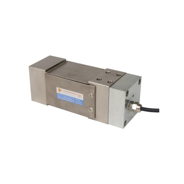

METRAVON MV-LC0055 is listed as a 4-20 mA platform load cell for the 50-800 kg family, with a 12-24 V DC supply entry. It is a candidate for a PLC current-input weighing channel, subject to confirmation of the delivered electrical configuration. The reference combines those current-output entries with a bridge-style circuit drawing. A safe integration decision requires the actual current-output terminal diagram, not a connection inferred from a neighbouring bridge model.
Confirm the 4-20 mA platform load cell wiring before selecting the PLC channel
Ask whether the supplied version uses a two-wire loop or separately powered output, and obtain terminal functions, polarity and the supported input load. The reference does not settle those points or establish galvanic isolation. Match the PLC active or passive input arrangement to the delivered circuit. Do not connect the 12-24 V supply to wires using the bridge excitation and signal colours shown in the generic diagram. The bridge resistance entries in that same table are not a documented permissible current-loop load.
Define what the current represents in this platform
State whether the requested 4 mA and 20 mA values correspond to gross weight, net weight or another agreed calibrated interval. Include tray dead load, working range, units and any required tare procedure. The available entry does not define those endpoint settings, fault currents or overload indication. Agree the signal mapping in the offer, then check the measured current against the PLC raw value and displayed weight. A correct current-to-display conversion does not by itself prove that the mechanical platform is transferring load correctly.
| Item | Value | Selection notes |
|---|---|---|
| Documented signal entry | 4-20 mA | Delivered circuit, terminal functions and input-load limit need confirmation. |
| Documented supply entry | 12-24 V DC | Do not infer two-wire or separately powered topology. |
| Technical rated family | 50-800 kg | Agree actual rating and current-to-weight endpoint mapping. |
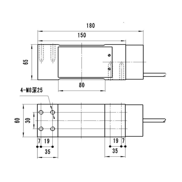
| Overall / secondary length references | 180 / 150 mm | The shorter reference is not the total installed envelope. |
| Side height / plan width | 65 / 60 mm | Reserve room for the cover, gland and attached tray. |
| Fixing-depth annotation | M8, 25 mm | Obtain permitted engagement; do not transfer the 0054 depth unchanged. |
Allow for the 180 mm body instead of assuming a bridge-cell replacement fits
The outline gives 180 mm overall length, a separate 150 mm reference, 65 mm side height and 60 mm plan width. It also shows a covered side section and four M8 fixing positions with a 25 mm depth annotation. The attachment pattern includes 19 and 30 mm centre references. Review the complete base and tray connections, cover clearance and cable-gland access. Do not use the 150 mm reference as the full outer envelope or assume the same screw engagement as the exposed-body MV-LC0054.
Separate electrical checks from installed weighing checks
Commission the approved supply and current circuit first, using the delivered instructions and appropriate test equipment. Then apply agreed physical reference weights, compare current and PLC indication, and test unloaded return and off-centre positions. If an electrical input test passes but the loaded tray does not, inspect the attachments and unintended contacts before changing endpoint scaling. No update rate, filter response or fault-detection behaviour is specified by the current-output label; those requirements need explicit confirmation if the weight drives process decisions.
Include enclosure and support conditions in the quotation
The listed entries include IP67, 0.05% FS precision, 0.02% FS per 10 deg C temperature effect and -40 to +85 deg C operating temperature. Confirm which electrical configuration those limits cover and how the cable termination is protected. The 200% FS safe-load figure is a sensor limit, not a rating for the attached tray or a dropped-object test. Request the permitted platform dimensions and provide the most distant loading positions so corner adjustment is not assumed to cover an arbitrary platform.
If the installation already has a weighing bridge reader, the MV-LC0054 mV/V platform arrangement is another channel to assess. Its 150 mm body reference and different attachment-depth annotation must also be checked; it is not an electrically interchangeable substitute.
PLC inputs, endpoint mapping and wiring confirmation
Q1. Can it be wired as a standard two-wire transmitter?
That topology is not confirmed by the available drawing. Obtain the diagram for the actual 4-20 mA version and match it to the PLC input type. The existence of a current-output entry does not identify the number of active conductors.
Q2. Does 4 mA automatically mean an empty tray?
Not unless that mapping is included in the delivered configuration. Define gross or net weight, tray tare and the required endpoints before ordering. Verify those settings using physical reference weights as well as the PLC conversion.
Q3. Can the 400-ohm input entry be used as the loop-load limit?
No. That entry appears with the bridge-style data and does not document a current-loop load allowance. Request the current-output electrical specification rather than calculating a permissible PLC load from a bridge resistance.
Q4. What should be included in the enquiry for an existing PLC?
Provide its analogue input model and active/passive arrangement, available supply, required weight interval and tare method. Add the tray and base drawings, available 180 mm envelope and loading positions. Ask the offer to include the current-output diagram and endpoint definition.
