


 Chinese
 Spanish
 Russian
 Portuguese
 French
 German
 Indonesian
 Thai
 Vietnamese
 Arabic
 Italian
 Turkish
 Polish
 Japanese



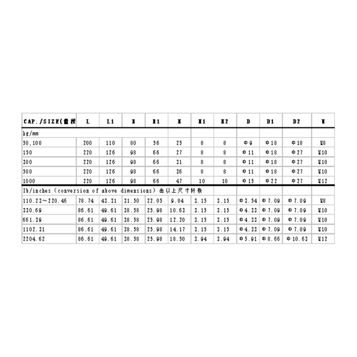
METRAVON MV-LC0056 is a platform load cell with multiple attachment features and a capacity-dependent mounting table. The 50-1000 kg family does not retain one body height across the range. A capacity increase can change platform height, thread size and clearance even where two versions share the same overall length. Select the actual rated row before making the base, tray or associated mating features.
Select the platform load cell row before freezing the scale height
For 50 and 100 kg, the metric table gives L200 mm, L1 110 mm, width B80 mm and H25 mm. The 150, 300, 500 and 1000 kg rows use L220 mm, L1 126 mm and B98 mm, but H changes through 27, 31, 36 and 47 mm. Thus a 300 kg and a 500 kg version share several plan dimensions while differing in height. Keep the required tray datum, underside clearance and any overload-stop arrangement tied to the selected rated body.
| Item | Value | Selection notes |
|---|---|---|
| 50 / 100 kg: L / B / H / M | 200 / 80 / 25 mm / M8 | L1 reference is 110 mm; use the full mating-hole detail. |
| 150 kg: L / B / H / M | 220 / 98 / 27 mm / M10 | Height is not shared with the higher rows. |
| 300 kg: L / B / H / M | 220 / 98 / 31 mm / M10 | Check tray datum and clearance when retaining a base. |
| 500 kg: L / B / H / M | 220 / 98 / 36 mm / M10 | Same plan size does not establish equal installed height. |
| 1000 kg: L / B / H / M | 220 / 98 / 47 mm / M12 | Thread and other hole references change at this rating. |
| Precision / enclosure entry | 0.05% FS / IP67 | Agree actual platform acceptance and exposure separately. |
Read the separate hole features instead of counting visible openings
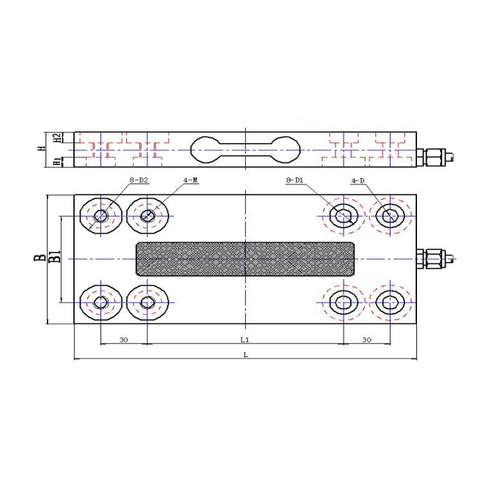
The outline distinguishes four D features, eight D1 features, eight D2 features and four M annotations. Their purposes and the complete mating hardware must be confirmed from the rated attachment detail. The table lists M8 for 50/100 kg, M10 for 150/300/500 kg and M12 for 1000 kg; D changes from 9 to 11 to 15 mm across those groups. Do not translate a clearance diameter directly into a screw size or assume every concentric circle is another fixing hole. Submit the base and tray patterns with their contact faces identified.
Keep tray clearance through the expected load positions
The open parallel-beam section and relieved surfaces must not touch a cover, continuous bed or mounting plate as the tray is loaded. Include any cable gland, guard and permitted movement in the clearance review. The reference describes factory corner adjustment within a specified loading plane, without supplying a maximum platform dimension. A wide tray can impose a different moment from a compact one at the same gross weight. Obtain the accepted platform envelope for the chosen rating and define the positions used for installed checks.
Match the bridge channel and useful weighing interval
The electrical specification is 2.0 +/-0.001 mV/V at 10-12 V DC excitation, with 400 +/-20 ohms input and 350 +/-5 ohms output resistance. Provide the tray tare, required net weights and indicator input range. Increasing rated capacity can reduce how much signal represents a small net change, so confirm the useful installed result rather than choosing the largest body automatically. Use the delivered wiring record to resolve the conflicting source signal-colour annotations before connecting the channel.
Verify height changes before adjusting position errors
After assembly, check that the new height has not brought the tray onto a stop or guard. Compare repeated reference weights at the agreed centre and off-centre positions, then unloading return. Investigate contact and fixture stiffness before using instrument correction to hide a mechanical difference. The 0.05% FS precision entry and 0.02% FS per 10 deg C temperature entry do not supply a completed-scale corner-error guarantee. IP67, -40 to +85 deg C operation and 200% FS safe load also do not define platform impact performance or a fastening torque.
Height changes and multiple hole references
Q1. Will a 500 kg version fit a scale built around the 300 kg version?
The listed plan sizes agree, but body height changes from 31 to 36 mm. Compare all attachment details, tray datum and clearances before deciding. A five-millimetre change can also affect a retained stop or adjacent guide.
Q2. Are all the concentric circles fixing holes?
The drawing uses several diameter and thread annotations for different features. Obtain the complete rated attachment view instead of assigning a fastener to every circle. The base and tray need the correct contact and engagement, not only a matching hole count.
Q3. Is the 1000 kg unit preferable for a light package scale?
Not automatically. Its larger height and M12 reference change the mechanics, and the required small net-weight result still needs verification. Choose the rating from tare, useful weights, load positions and handling conditions together.
