


 Chinese
 Spanish
 Russian
 Portuguese
 French
 German
 Indonesian
 Thai
 Vietnamese
 Arabic
 Italian
 Turkish
 Polish
 Japanese


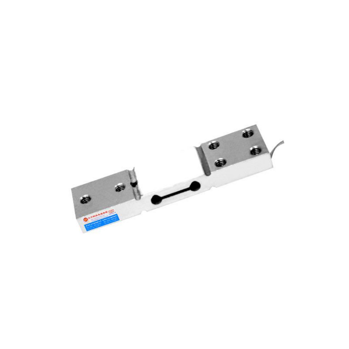

METRAVON MV-LC0057 is a single-point load cell with a double-hole parallel-beam structure for compact platforms. The reference describes corner-error adjustment for a specified loading plane and a 20-100 kg range. This makes platform dimensions and off-centre weight checks important selection inputs. The 99 mm sensor length alone does not establish how large a tray may be fitted or what corner error the completed scale will achieve.
Confirm the platform envelope before choosing the single-point load cell
Provide the tray length and width, its dead weight, maximum contents and the most distant permitted loading positions. State whether a container can overhang the tray or strike a stop during placement. The available reference does not specify a maximum platform size or numerical eccentric-load limit. Ask for the permitted platform envelope for the selected rating, rather than extending a factory corner-adjustment statement to any tray geometry. A larger platform changes the moments applied to the beam even if gross weight is unchanged.
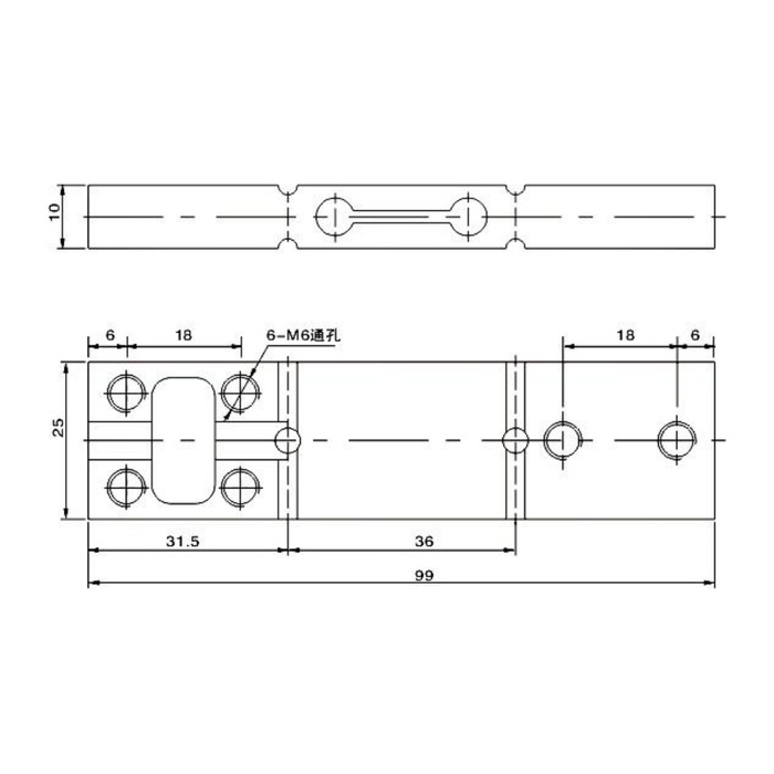
Keep the two end attachments separate across the sensing section
The outline gives a 99 mm length, 25 mm width and 10 mm thickness reference. It shows six M6 callouts, including an asymmetric arrangement of four positions at one end and two at the other. The wording of the callout and the complete attachment specification need confirmation before fasteners are ordered. Submit the platform and base views together so the fixed and moving ends can be identified. Do not bridge the thin central section with a bracket or put a supporting pad beneath it to make the tray feel stiffer.
Test centre and corner readings with the actual tray
After installing the approved attachments, place an agreed reference load at the centre and the specified off-centre positions. Compare the readings and unloading return with the normal tray, stops and cable restraints fitted. If a reading changes when the tray touches a housing, remove that unintended contact before adjusting the instrument. The listed precision is 0.05% FS. It is not a promised percentage of a light package weight or a substitute for checking the complete tray assembly at the positions the operator uses.
| Item | Value | Selection notes |
|---|---|---|
| Capacity family | 20-100 kg | Include the tray dead weight and normal net weighing interval. |
| Length / width / thickness | 99 / 25 / 10 mm | Confirm the complete attachment and clearance drawing. |
| End attachment annotations | Six M6 callouts | The four/two position layout needs matched base and tray views. |
| Output sensitivity | 2.0 +/-0.001 mV/V | Check indicator span at the actual useful weights. |
| Precision / temperature entry | 0.05% FS / 0.02% FS per 10 deg C | Neither entry supplies a maximum tray size or corner-error allowance. |
| Protection entry | IP67 | Check the external reader and termination separately. |
Specify the small-scale signal channel and enclosure
The sensor uses 10-12 V DC excitation and a rated bridge output of 2.0 +/-0.001 mV/V. Its input resistance is 400 +/-20 ohms; output resistance is 350 +/-5 ohms. Check the indicator input and excitation against these entries, then calibrate in the required weight units. Delivered terminal identification is needed because the available signal-colour legend conflicts with the circuit sketch. IP67 and -40 to +85 deg C are sensor entries, not a cleaning approval for the tray electronics or cable termination. No native RS485 or 4-20 mA output is specified for this bridge.
Keep handling impacts out of the weighing specification
Identify how products are placed on the tray and how an operator might lean or press on its edge. Mechanical stops need a defined design and adjustment; no stop clearance or fastening torque is given in the reference. The 200% FS safe-load figure does not establish impact survival for a dropped package. Include the intended smallest net weight and acceptable installed readings in the enquiry so the rated capacity is not chosen only for occasional misuse at the expense of the normal weighing task.
Tray size and off-centre readings
Q1. Can a larger tray be fitted if its gross weight stays below the rating?
Gross weight is only one condition. A longer or wider tray changes the leverage at off-centre positions. Obtain a permitted platform envelope and verify the proposed tray before relying on the single-point corner-adjustment description.
Q2. Should a pad be added under the centre to reduce tray movement?
That can bypass the sensing section or restrain its intended deflection. Review the tray stiffness and end attachments instead. Any additional support must be part of an approved arrangement, not an improvised contact beneath the beam.
Q3. What should be checked when the same weight reads differently near the edge?
First inspect housing contact, stop engagement, tray rigidity and the two end attachments. Then repeat the agreed positions with the same reference load. A centre-only recalibration cannot establish that an off-centre mechanical problem has been removed.
