


 Chinese
 Spanish
 Russian
 Portuguese
 French
 German
 Indonesian
 Thai
 Vietnamese
 Arabic
 Italian
 Turkish
 Polish
 Japanese



METRAVON MV-LC0058 is a shear beam load cell for heavy platform and industrial weighing structures. Its reference applications include vehicle, rail and hopper weighing, but each installation still needs its own load-introduction and restraint design. The technical family covers 0.5-25 t, while the available dimensional table lists 2, 3, 5, 10, 15, 20 and 25 t groups. A lower-range unit cannot be fitted from those larger-capacity dimensions by assumption.
Choose the rated shear beam load cell before retaining an existing base
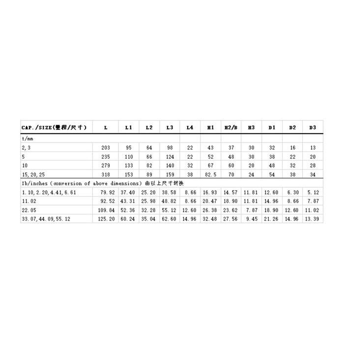
The metric table gives overall length L203 mm for 2/3 t, L235 mm for 5 t, L279 mm for 10 t and L318 mm for 15/20/25 t. H1 rises across those groups from 43 to 52, 67 and 82.5 mm. The D3 fixing-hole references also change from 13 to 20, 28 and 34 mm. These are meaningful changes to the base, fasteners and installed scale height. Use the full selected outline, with its tolerances and mating hardware, before declaring an old support reusable.
| Item | Value | Selection notes |
|---|---|---|
| 2 / 3 t group: L / H1 / D3 | 203 / 43 / 13 mm | Use the full outline and specified mating load hardware. |
| 5 t group: L / H1 / D3 | 235 / 52 / 20 mm | A change of rating can require a different base and height. |
| 10 t group: L / H1 / D3 | 279 / 67 / 28 mm | Do not transfer the smaller fixing pattern. |
| 15 / 20 / 25 t: L / H1 / D3 | 318 / 82.5 / 34 mm | Confirm the individual rated configuration within this group. |
| Technical family / dimension coverage | 0.5-25 t / 2-25 t listed | Request a rated outline for the lower capacities. |
| Listed sensor precision | 0.02% FS | Specify installed scale acceptance independently. |
Include the loading hardware, not just the beam body
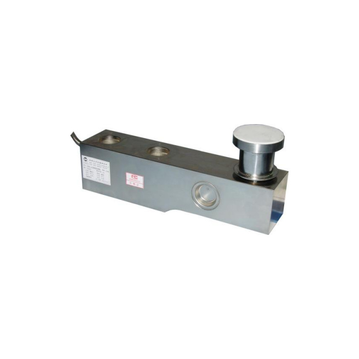
The reference photo shows a raised loading component at the opposite end from the cable. Identify which contact parts, seats and retainers are included in the quotation and how the measured reaction enters the beam. A photograph does not establish the complete delivered assembly or its lifting restraint. Check maintenance removal space and the contact condition of the existing support. Reusing a damaged seat can leave an otherwise correct replacement cell operating under an unintended force path.
Size for the worst individual reaction in the actual scale
Provide the support positions, permanent structure weight and the governing loaded positions. On a vehicle scale, a moving wheel position or uneven distribution can change individual reactions; a rail or hopper installation has different load cases. Do not select every cell from gross total divided by support count without checking those cases. The 0.02% FS precision entry belongs to the sensor specification. It does not certify a road or rail weighing installation, establish dynamic weighing performance, or replace the project acceptance procedure.
Check the retained bridge network after a mechanical replacement
The documented electrical values are 400 +/-20 ohms at the input and 350 +/-5 ohms at the output, with 2.0 +/-0.001 mV/V sensitivity and 10-12 V DC excitation. Record the ratings and sensitivities of the other cells, junction-box trims and indicator configuration. Shared nominal sensitivity does not establish a matched multi-cell network. Obtain delivered wire functions before connecting the replacement because the signal-colour legend and circuit differ. Verify the indicated loading direction before adjusting corner balance or span.
Verify the repaired platform at its real loading positions
Review clearances and restraints, then use the agreed reference loads and positions to compare repeatability and unloaded return. Check the areas most affected by the repaired support rather than accepting a stable empty display alone. The enclosure entry lists IP67/IP68 alternatives; confirm the supplied variant and any immersion conditions. The 200% FS safe-load limit is not an overload test requirement for the platform. Operating temperature is listed as -40 to +85 deg C, without a separate approval for every cable termination or pit environment.
For a retrofit involving a stepped beam, compare the MV-LC0060 reference profile and hole pattern. Its separate outline and precision entry need their own review even where the technical capacity ranges overlap.
Heavy-platform replacements and loading hardware
Q1. Can a 10 t version replace a 5 t version on the same base?
The metric groups have different lengths, heights and fixing-hole references. Compare the full assemblies and support reactions first. A stronger rating is not evidence of mechanical interchangeability or equivalent useful weighing performance.
Q2. Is the loading component in the photo included automatically?
The photo does not define a supply list. Identify the required loading parts, seats and restraints in the enquiry and have the offer list them. Confirm the contact geometry of any retained part before combining it with a new beam.
Q3. Does the rail-scale application reference establish dynamic weighing accuracy?
No test speed, sampling performance or completed-scale acceptance result is provided by that application reference. A dynamic rail project needs its own verified system design and acceptance method. Do not use the static sensor precision entry as the system result.
