


 Chinese
 Spanish
 Russian
 Portuguese
 French
 German
 Indonesian
 Thai
 Vietnamese
 Arabic
 Italian
 Turkish
 Polish
 Japanese


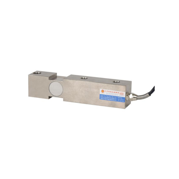

METRAVON MV-LC0060 is a cantilever beam load cell with a stepped upper profile in its reference photo. It is listed for a 0.5-25 t family and weighing supports such as low platforms and hoppers. The outline supplied with the reference is one dimensioned arrangement, not a capacity-by-capacity installation table. A buyer should resolve the selected rated body and loading hardware before treating its 200 mm length as a universal replacement envelope.
Read the cantilever beam load cell hole pattern as a complete arrangement
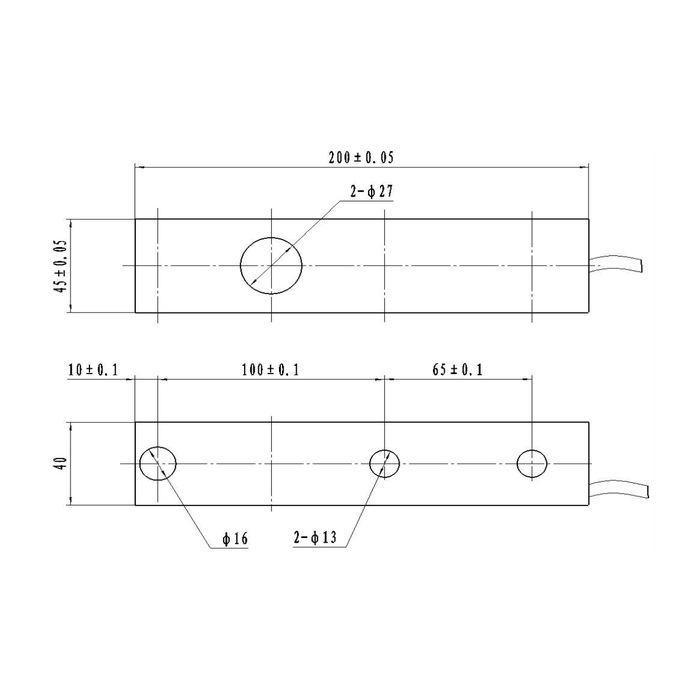
The reference shows a 200 +/-0.05 mm overall length, a 45 +/-0.05 mm side-height reference and a 40 mm plan width. Along the plan view, the first hole centre is 10 +/-0.1 mm from the end, followed by 100 +/-0.1 and 65 +/-0.1 mm centre spacings. Hole callouts distinguish a diameter-16 opening from two diameter-13 openings. Confirm the function of each opening and the approved fixed-end and loaded-end parts; three holes do not mean three interchangeable fixing positions.
| Item | Value | Selection notes |
|---|---|---|
| Technical family | 0.5-25 t | Match the offered rating to its own outline and hardware. |
| Reference length | 200 +/-0.05 mm | A single outline is available, not a dimensional promise for every rating. |
| Height / plan width references | 45 +/-0.05 / 40 mm | Show the stepped contact and proposed supporting faces in section. |
| First hole offset | 10 +/-0.1 mm | Retain the complete hole-position chain on the drawing. |
| Successive centre spacings | 100 +/-0.1 / 65 +/-0.1 mm | Confirm which positions fix the beam and which introduce load. |
| Hole references | 16 mm / two 13 mm | No fastener size or torque is inferred from hole diameter. |
Do not flatten the stepped profile with an unapproved spacer
The photo and outline need to be reviewed with the actual base, loading head and mating structure. A spacer that touches a relieved area or extends into the active section can alter the force route. Show any height compensation and the required contact faces in section instead of filling every visible gap. The reference includes a movable-head description, but it does not define every supplied head or retainer. Ask which parts are included and how the step relates to the installed assembly.
Select a capacity without assuming the reference envelope is shared
For a 0.5 t order or a 25 t order, request the matched rated drawing and permissible installation arrangement. The broad family label does not prove that the same holes, height, fasteners and loading components apply to both. Include maximum support reaction, permanent dead load and any unloading or lifting condition. If capacity is increased during a retrofit, review the existing steelwork and attachments rather than changing only the cell and display scale.
Check the bridge and loading response before returning to production
The reference channel has 2.0 +/-0.001 mV/V sensitivity, 400 +/-20 ohms input resistance and 350 +/-5 ohms output resistance, powered by 10-12 V DC excitation. Use the delivered connection record to establish terminal functions and force sign; the available wire-colour legend is inconsistent with its circuit. Test the intended reference weights with the final load head and restraints installed. A stable empty reading cannot demonstrate correct span where a spacer or guide carries part of the applied load.
State environmental and installed weighing requirements explicitly
IP67 is the listed enclosure entry; IP68 should not be borrowed from a similar beam family. The operating-temperature entry is -40 to +85 deg C. Specify any cleaning exposure, pit water, cable-junction location and corrosion concern in the quotation. The 0.05% FS precision and 0.02% FS per 10 deg C temperature figures do not define the whole hopper or platform result. Agree repeat-load checks and unloading return at the useful working points. The 200% FS safe-load limit does not replace support or overload-stop design.
Stepped bases and the reference hole pattern
Q1. Are the 200 mm dimensions valid for every available capacity?
The reference does not provide that confirmation. Request the released outline for the actual quoted rating. A family range and one drawing cannot establish unchanged geometry across a fifty-to-one capacity span.
Q2. Can all three top holes be used to bolt the beam down?
Their load and fixing functions must follow the approved arrangement. Restraining a position intended to introduce the measured load can change the response or bypass the sensing section. Submit the base and top structure before choosing the fastening positions.
Q3. Will a spacer make it interchangeable with a flat beam?
Not by height matching alone. Check where the spacer contacts, what carries the load and whether the active section remains free. The hole pattern, rated reaction, head assembly and bridge channel also need to match the installation requirement.
