


 Chinese
 Spanish
 Russian
 Portuguese
 French
 German
 Indonesian
 Thai
 Vietnamese
 Arabic
 Italian
 Turkish
 Polish
 Japanese



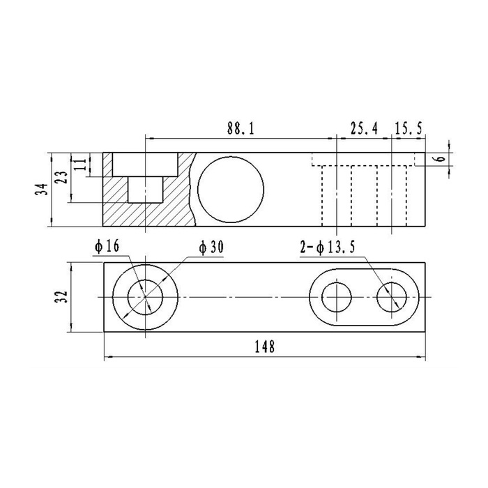
METRAVON MV-LC0061 is a cantilever beam load cell in the 0.5-3 t capacity range. Its catalogue drawing shows a 148 mm long body, a nominal 32 mm width and two 13.5 mm mounting holes. For a scale retrofit, check this geometry before comparing electrical sensitivity: another 2 mV/V beam is not necessarily a mechanical replacement.
Compare the fixing pattern and load contact
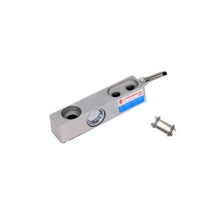
The two mounting holes are shown at 25.4 mm centres. Check the loading contact, base clearance and cable exit as well as the fixing holes against the actual scale frame. Obtain the capacity-specific drawing before drilling or machining; a photograph cannot establish the complete fit.
The MV-LC0050 beam has a different published envelope, including a 203 mm overall length. These two models should not be substituted solely because both use a nominal 2 mV/V bridge output. Keep the load contact and mounting arrangement within the selected model's design.
Capacity and bridge characteristics
| Specification | MV-LC0061 |
|---|---|
| Capacity range | 0.5-3 t |
| Output sensitivity | 2.0 +/-0.001 mV/V |
| Specified excitation | 10-12 V DC |
| Bridge input resistance | 400 +/-20 ohm |
| Signal output resistance | 350 +/-5 ohm |
| Catalogue accuracy | 0.05% of full scale |
| Operating temperature | -40 to +85 deg C |
| Protection listing | IP67/IP68; confirm the rating of the supplied configuration. |
| Safe load limit | 200% of full scale |
The safe load limit is not an extended calibrated range or permission for repeated overload. Select the rated capacity for the maximum design reaction, including dead load and the project's shock conditions. The published accuracy likewise must not be treated as the error allowance for a whole multi-support scale.
Commission the replacement on the installed scale
Keep a record of the previous sensor's capacity, wiring, instrument settings and reason for replacement. After fitting, examine the unloaded signal before adjusting the indicator. A large change may come from trapped hardware or preload, not simply from a different electrical zero.
Compare responses with the same reference load at the required positions, then complete the instrument's calibration procedure. Keep the results with the final wiring record. A replacement that produces the correct centre-load reading can still have an unacceptable corner response if the loading arrangement binds.
Retrofit questions
Q1. Can a 5 V weighing indicator be used without further confirmation?
The sensor specification lists 10-12 V DC excitation. Do not approve a lower-excitation pairing from the 2 mV/V label alone. Obtain confirmation of performance at the proposed voltage and check the indicator's input sensitivity and bridge-drive capability before ordering the combination.
Q2. Is a larger capacity always a better replacement?
A higher rating can reduce the signal produced by the normal working load and require different calibration. It also does not correct poor alignment or mechanical impact. Choose capacity using the actual forces and required weighing resolution, then verify both the mechanical and electrical fit.
For an MV-LC0061 replacement quotation, attach the old sensor drawing or dimensioned photographs, loading hardware details, required capacity and instrument specification. State whether alloy steel or stainless steel is required and ask for the quoted protection rating to be identified explicitly.
