


 Chinese
 Spanish
 Russian
 Portuguese
 French
 German
 Indonesian
 Thai
 Vietnamese
 Arabic
 Italian
 Turkish
 Polish
 Japanese



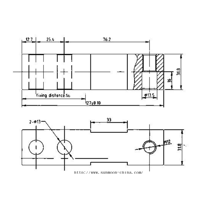
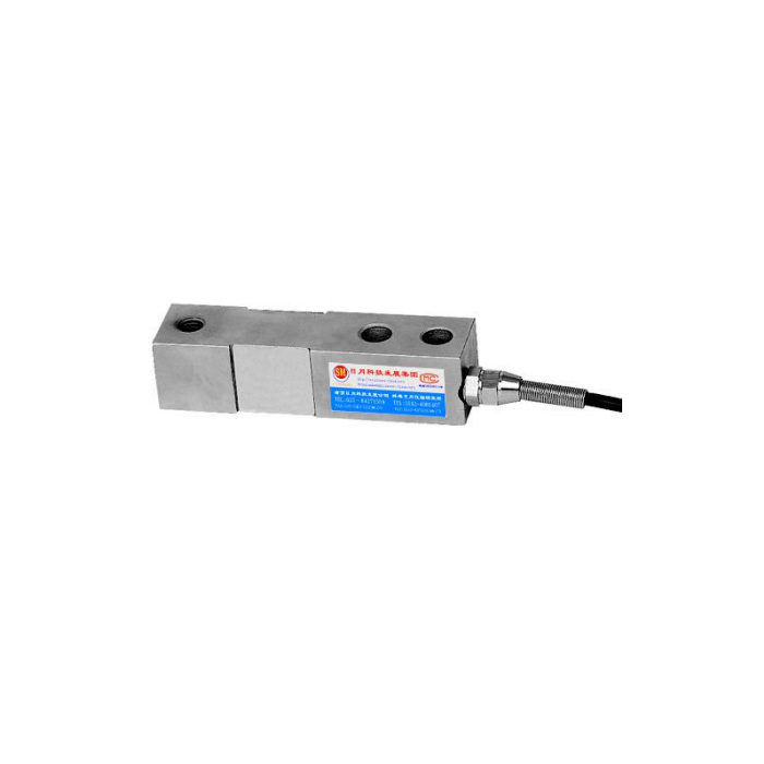
METRAVON MV-LC0062 is a compact beam load cell for restricted-height weighing supports in the 100-500 kg family. Its reference outline shows two fixing-hole positions at one end and an M12 annotation at the load end. The cable leaves at the fixing side. Correct selection depends on retaining clearance around the reduced section and defining the load-end fitting, rather than using the outer block dimensions alone to make a mounting pocket.
Give the load-end M12 annotation a complete connection definition
The drawing marks M12 but does not supply a pitch, engagement requirement or tightening torque. Its section also includes a diameter-13.5 feature and a 16 mm depth reference. These callouts should be read together on a confirmed installation drawing; a nearby diameter must not be converted into an assumed thread or a new loading contact. Submit the mating part and ask how it introduces the vertical reaction, how it is retained and which surfaces must remain clear during weighing.
Support the compact beam load cell without bridging the reduced section
The metric outline gives 127 +/-0.10 mm overall length and 31.8 mm height and width references. The two diameter-13 fixing positions have a 12.7 mm end offset and 25.4 mm centre spacing. A further 76.2 mm spacing leads towards the load-end position. The drawing also labels a 56 mm fixing-distance reference and a 33 mm reduced-section feature. Obtain the permitted supporting footprint before making a continuous bed beneath the beam; filling the relieved area can turn a clearance into an unintended support.
| Item | Value | Selection notes |
|---|---|---|
| Capacity family | 100-500 kg | State dead load, useful net interval and greatest support reaction. |
| Overall length | 127 +/-0.10 mm | The cable and mating load hardware require extra envelope space. |
| Height / width references | 31.8 / 31.8 mm | The reduced section must not acquire an unintended support. |
| Fixing positions | Two 13 mm holes | End offset 12.7 mm and centre spacing 25.4 mm are reference details. |
| Load-end annotation | M12 | Obtain the full thread, engagement and mating-part definition. |
| Reduced-section reference | 33 mm | Confirm supporting footprint rather than filling the relief. |
Choose the working interval before increasing capacity
A small hopper or low platform may impose substantial dead load while requiring a much smaller net weight change to be measured. Provide both values and the maximum individual support reaction. The family range is not proof that any arbitrary rating between 100 and 500 kg is offered. The 0.05% FS precision entry is based on the selected full scale, not a fixed percentage of each small addition. Ask the quotation to identify the actual rated version and agree installed checks near the useful process points.
Keep cable restraint away from the measured reaction
Show the cable gland, spring protection and free route beside the fixed end. Secure the cable where its movement cannot pull on the beam or contact the loaded structure. The sensor requires a bridge input: 10-12 V DC excitation, 2.0 +/-0.001 mV/V sensitivity, 400 +/-20 ohms input resistance and 350 +/-5 ohms output resistance. For a PLC analogue channel, identify the separate conditioner and its scale. Use delivered wire functions rather than the conflicting reference signal-colour annotations.
Check the installed load path after the final head is fitted
Apply agreed reference weights through the actual mating part, compare repeated readings and check return after unloading. Inspect whether a guide, pipe, guard or supporting bed starts carrying load as the structure moves. Perform these checks before hiding a mechanical offset with zero adjustment. The protection entry lists IP67/IP68 alternatives and needs an identified delivered version, including any immersion conditions. Operating temperature is -40 to +85 deg C. The 200% FS safe-load entry does not define an overload clearance or a rating for the unconfirmed M12 fitting.
The MV-LC0063 beam reference explicitly labels an M12 x 1 load-end connection and a different width. Compare the complete head and support drawings; the shared 127 mm length does not make these two models interchangeable.
M12 fittings and clearance beneath the beam
Q1. Is the load-end connection the same as an M12 x 1 beam?
The available annotation does not establish that pitch. Compare the complete delivered threads and loading parts before reusing a fitting from another model. Similar body length and nominal diameter do not establish a matching connection.
Q2. Can the whole bottom face sit on a flat support bar?
Confirm the permitted support footprint first. A bar extending beneath the active or relieved section can change the load path as the beam moves. Use a section view to show exactly where contact is allowed and where clearance must be retained.
Q3. What should a compact hopper enquiry include?
Include the empty and full vessel weights, support layout, required net increment and the proposed load-end fitting. Show pipe restraints and the nearby cable route. Request the rated drawing and a list of supplied mounting parts so the small beam is not mistaken for a complete vessel module.
