


 Chinese
 Spanish
 Russian
 Portuguese
 French
 German
 Indonesian
 Thai
 Vietnamese
 Arabic
 Italian
 Turkish
 Polish
 Japanese


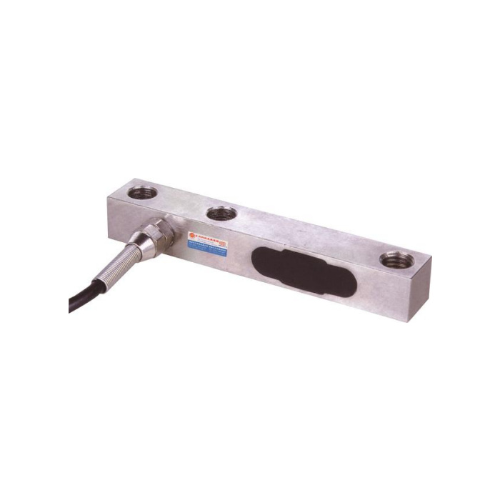

METRAVON MV-LC0063 is a cantilever beam load cell documented for low-platform, hopper, silo and forklift-scale arrangements. The reference family covers 100-1000 kg and uses a movable loading head. Its compact beam can be useful where the support height is restricted, but the quoted sensor should be matched to the fixed end, load introduction and clearance beneath the sensing section. An exposed beam is not a complete tank-support module.
Fit the cantilever beam load cell around the intended force path
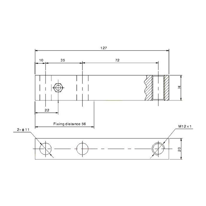
The reference outline gives a 127 mm overall length and a 20 mm width, with two diameter-11 fixing-hole callouts and an M12 x 1 connection at the loading end. A 56 mm fixing-distance annotation and several other offsets appear in the side view. The height is labelled H without a numerical value on that drawing. Request the complete rated outline and approved fixed-end arrangement before drilling the base or setting the platform height. Confirm the value of H and the function of each opening before releasing the base for manufacture.
| Item | Value | Selection notes |
|---|---|---|
| Capacity family | 100-1000 kg | State the required rating and maximum individual reaction. |
| Length / width references | 127 / 20 mm | Height H remains unspecified in the available outline. |
| Fixing holes / load-end connection | Two 11 mm holes / M12 x 1 | Confirm the fixing view and matched loading head. |
| Rated sensitivity | 2.0 +/-0.001 mV/V | Use the delivered calibration data for the indicator setup. |
| Input / output resistance | 400 / 350 ohms | Tolerances are +/-20 and +/-5 ohms respectively. |
| Listed precision | 0.02% FS | Installed-scale performance also depends on mechanics and calibration. |
Allow the loading head to function without becoming a restraint
The movable head is part of the load-introduction arrangement, not permission to apply an arbitrary side force. Show the head, mating bracket, retaining parts and direction of platform movement in a section drawing. A head that binds against a bracket, or a beam that touches a guard beneath it, can create another route for force. For a hopper, check pipe connections and lateral restraints as separate mechanical features. None of the available entries supplies a numerical lateral-load allowance or a complete anti-lift design.
Choose capacity from the largest support reaction
Include the platform or vessel dead weight, maximum contents and the greatest reaction at an individual support. Unequal loading and changes in the centre of gravity can make that reaction larger than total weight divided by the number of cells. In a forklift installation, also identify the attachment geometry and operating load cases; the application reference is not an approval for a particular truck. The 0.02% FS precision entry describes the sensor specification, not a guaranteed finished-scale result under moving or constrained loads.
Match the beam to its weighing channel
The bridge specification is 2.0 +/-0.001 mV/V with 10-12 V DC excitation, 400 +/-20 ohms input and 350 +/-5 ohms output resistance. Check the indicator excitation budget and the actual connected sensors before retaining an old junction-box adjustment. A PLC current input needs a suitable weight transmitter rather than the raw bridge connection. Obtain the delivered terminal functions: the available colour list and circuit identify the signal pair differently. Establish force sign and reference readings before accepting a calibration.
Check the support before correcting a drifting zero
Inspect for binding head parts, contact beneath the beam, loose fixing and cable pull. Repeat the agreed load points and unloading return after those conditions are corrected, with normal restraints in place. The reference lists -40 to +85 deg C, a 200% FS safe-load limit and IP67/IP68 alternatives. Identify the delivered protection version and any immersion conditions; the higher code is not automatic for every configuration. Safe overload is not a commissioning target or a substitute for mechanical stop design.
Loading heads and low-platform installations
Q1. Can this beam be bolted directly under a hopper leg?
Only with an approved support and load-introduction arrangement. A hopper also needs its lateral restraint, lifting protection and pipe forces addressed. The beam and movable head alone do not define a complete vessel mounting system.
Q2. What if the existing bracket has an ordinary M12 thread?
Check the pitch explicitly. The reference load-end connection is M12 x 1, so the nominal diameter does not confirm a fit. Obtain the head and mating-part detail before reusing or modifying the bracket.
Q3. What should accompany a low-platform scale enquiry?
Send the platform plan, support locations and maximum corner reactions, plus the available height and loading-head section. Include the required weighing interval and the indicator arrangement so that the mechanical layout and electrical channel can be reviewed together.
