


 Chinese
 Spanish
 Russian
 Portuguese
 French
 German
 Indonesian
 Thai
 Vietnamese
 Arabic
 Italian
 Turkish
 Polish
 Japanese


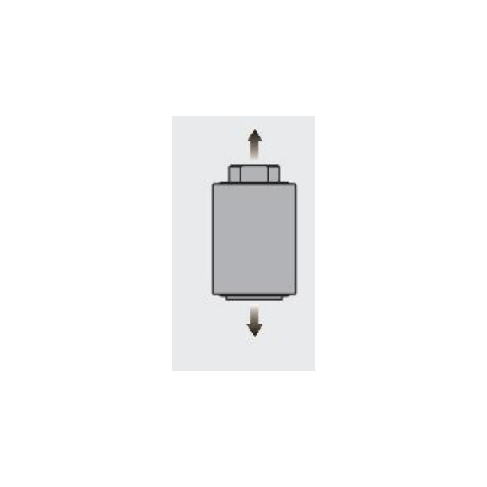

METRAVON MV-LC0064 is a tension and compression load cell for an axial force train in automation or test equipment. Unlike a compression button that merely has a retaining stud, this model is explicitly described for both loading directions. The documented family is 2-20 t. Selection must include the two threaded attachments, the forces applied in each direction and the bridge reader, not only the largest displayed force.
Define both directions before selecting the tension and compression load cell
State the working tension, working compression, preload and maximum credible force during reversal. If the test result depends on a small force around zero, identify those acceptance points separately from the maximum range. A bidirectional description does not establish identical error in every fixture or remove the need to check each direction. Specify loading and unloading references in tension and compression with the actual couplings fitted. The available data does not define a reversal fatigue life or a dynamic test bandwidth.
Connect the threaded ends without introducing bending
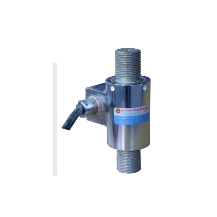
The reference outline identifies M30 x 2 connections at both ends, an overall axial length of 149 mm and a 35 mm end projection reference. The body view also shows 53 and 76 mm envelope references. Confirm the full connection tolerances, usable engagement and method of holding the body during assembly. Include the side cable housing and coupling movement in the installation envelope. Threaded attachments that are forced out of line can impose bending even when the sensor itself is specified for tension and compression.
Retain the actual excitation and bridge values
The recommended excitation is 5-12 V DC or AC, while 15 V is listed as a maximum, not the normal design setting. The reader must support the selected excitation method. Input resistance is 780 +/-5 ohms and output resistance is 700 +/-2 ohms. Rated sensitivity is nominally 2.0 mV/V; its table expresses the tolerance as a percentage and the quotation should reproduce that tolerance unambiguously. Do not replace it with an assumed absolute +/-0.1 mV/V. Obtain the supplied wiring record because the reference signal-colour list and circuit disagree.
| Item | Value | Selection notes |
|---|---|---|
| Rated family | 2-20 t | Confirm the rated configuration for tension and compression. |
| End connections | M30 x 2 reference | Check engagement, tolerances and the complete force train. |
| Axial length / end projection | 149 / 35 mm | Allow separately for couplings and side cable hardware. |
| Recommended excitation | 5-12 V DC or AC | Match the reader method; 15 V is a maximum entry. |
| Input / output resistance | 780 / 700 ohms | Listed tolerances are +/-5 and +/-2 ohms. |
| Safe / ultimate overload | 150 / 200% of rating | Do not confuse the ultimate entry with a safe operating load. |
| Operating temperature | -30 to +70 deg C | Review the whole test installation for its exposure. |
Separate operating limits from test-machine protection
Safe overload is listed at 150% of rated capacity and ultimate overload at 200%; those are different limits and neither is a routine test setting. Operating temperature is -30 to +70 deg C. Design the test equipment so an actuator fault or travel stop does not rely on the sensing body as its only protection. Check the couplings and surrounding structure independently. IP67 applies to the sensor entry, not automatically to the cable termination, acquisition cabinet or assembled test machine.
Ask for the certificate the project actually requires
The technical reference includes C3 and a standards reference, but that is not a supplied METRAVON approval certificate. If a regulated weighing or test project needs a particular certificate, request a document identifying the exact offered configuration and its scope before accepting the order. For force acceptance, agree the reference equipment, direction, force points and allowable results. Do not substitute a classification label for the installed verification procedure.
Force reversal, excitation and approval documents
Q1. Does a successful compression calibration also accept tension?
No. Verify the intended tension points and return through reversal as well. Coupling clearances, force alignment and the calibration arrangement can behave differently when the force direction changes.
Q2. Can the cell be used at 15 V because the reader offers that setting?
The reference lists 15 V as a maximum and recommends 5-12 V. Select a supported recommended setting and verify the reader configuration. A maximum voltage is not a reason to run the bridge continuously at that value.
Q3. Does the C3 entry prove that the offered unit has the required approval?
It does not replace a configuration-specific certificate. State the exact regulatory or contractual requirement and obtain the corresponding document before ordering. Keep that document check separate from force calibration of the installed test assembly.
Q4. What is needed to quote the two attachments?
Provide both mating drawings, required axial travel and force in each direction, available coupling space and the reader. Ask for the connection tolerances and engagement on the rated drawing; neither thread diameter nor visible stud length defines a safe attachment on its own.
