


 Chinese
 Spanish
 Russian
 Portuguese
 French
 German
 Indonesian
 Thai
 Vietnamese
 Arabic
 Italian
 Turkish
 Polish
 Japanese



METRAVON MV-LC0065 is a bellows load cell with a parallel-beam sensing structure and welded metal bellows. Its documented uses include belt scales, hoppers and platforms within a 10-500 kg family. The bellows protects the sensing section; it is not a surface for clamping, lifting or taking the platform reaction. The mounting dimensions change at the higher capacity group, so a range increase may require a new support rather than a new indicator setting alone.
Compare the bellows load cell mounting groups before replacing a beam
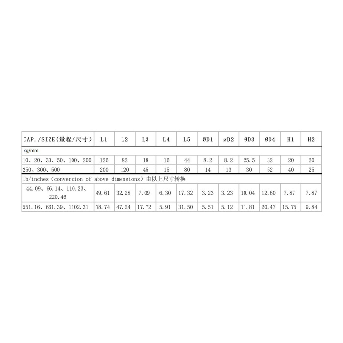
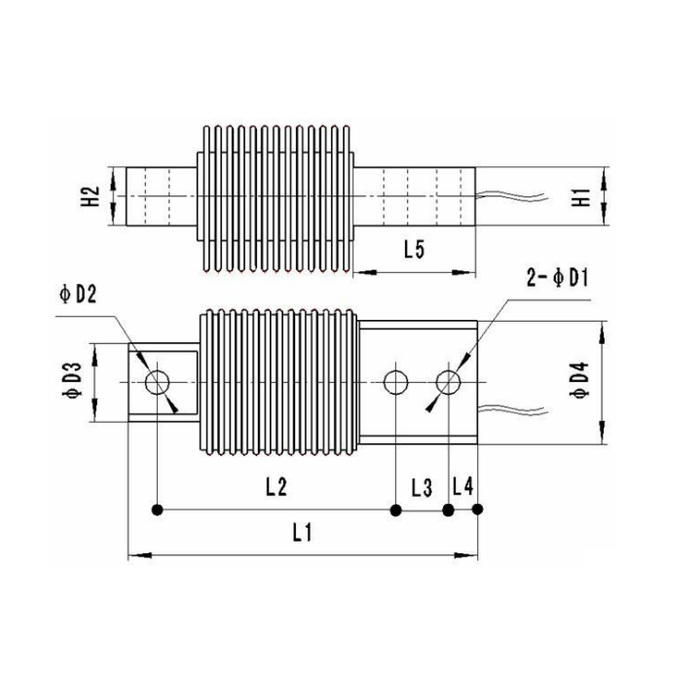
For the listed 10, 20, 30, 50, 100 and 200 kg versions, the metric table gives L1 126 mm, L2 82 mm and L5 44 mm. The 250, 300 and 500 kg group changes those references to 200, 120 and 80 mm. H1/H2 also change from 20/20 to 40/25 mm. Use the selected group with its outline to identify the fixing end, loaded end and support heights. The two groups are not confirmed drop-in replacements simply because their sensitivity is the same.
| Item | Value | Selection notes |
|---|---|---|
| Listed lower ratings | 10, 20, 30, 50, 100, 200 kg | L1/L2/L5 references: 126/82/44 mm. |
| Listed upper ratings | 250, 300, 500 kg | L1/L2/L5 references: 200/120/80 mm. |
| Lower / upper H1-H2 | 20-20 / 40-25 mm | Confirm the supporting and loading faces in the outline. |
| Lower / upper D1 hole reference | 8.2 / 14 mm | Other locating features differ; retain the complete rated drawing. |
| Sensitivity | 2.0 +/-0.01 mV/V | Check the actual span calibration after the mechanical work. |
| Input / output resistance | 400 / 350 ohms | Tolerances are +/-20 and +/-5 ohms. |
Leave the welded bellows clear of the machine structure
Show the support, load member, cover and debris path around the corrugated section. A cover must not press against the bellows as the beam deflects, and accumulated material must not bridge the moving section to the base. Route the cable so it does not pull on the sensing end. During maintenance, support and handle the assembly at approved solid features rather than gripping the bellows. The reference supplies no permissible clamp force or impact rating for the corrugations.
Describe the belt or hopper forces that enter the beam
For a belt scale, identify the weigh-frame geometry and the support reactions with the belt and idlers installed. A capacity figure alone does not determine throughput accuracy or remove the influence of belt mechanics. For a hopper, include tare, maximum contents and forces from connected pipes or restraints. Select for the greatest individual reaction and then check the useful weighing interval. The 0.02% FS precision entry and 0.02% FS per 10 deg C temperature entry are not finished-system acceptance limits.
Confirm the electrical and sealing configuration in the offer
The documented bridge is 2.0 +/-0.01 mV/V with 10-12 V DC excitation, 400 +/-20 ohms input and 350 +/-5 ohms output resistance. Specify the indicator and any junction box with the required sensor count. The listed enclosure alternatives are IP67/IP68; request the actual version and any IP68 exposure conditions rather than assuming both labels describe every supplied unit. The -40 to +85 deg C range does not establish cleaning-fluid compatibility. Delivered wire functions must resolve the disagreement between the available signal-colour legend and circuit.
Verify clearance and weighing with the normal covers fitted
Establish reference readings after the final supports, guards and cable restraints are installed. Check loading and unloading return, then inspect whether normal material accumulation or machine motion can create contact near the bellows. On a belt installation, use the agreed operational verification method rather than equating a static beam check with final material-flow acceptance. The 200% FS safe-load entry does not authorize overload commissioning or an uncontrolled belt shock.
Bellows clearance and capacity changes
Q1. Can a 300 kg version fit the base made for 100 kg?
The reference groups use different lengths, hole sizes and heights. Compare the full 250-500 kg outline to the existing frame before ordering. A transmitter adjustment cannot correct the changed support geometry.
Q2. Should a protective cover be tightened against the bellows?
No approved clamping arrangement is established for that section. Design the cover with verified clearance throughout the permitted motion and provide access for inspection. A cover that becomes a second support can alter the force reaching the sensing beam.
Q3. Does a static weight check prove belt-scale throughput accuracy?
It verifies only part of the measurement chain. Final acceptance must also address the operating belt and the agreed material or process reference. Define that method with the project rather than applying the sensor precision figure directly to accumulated throughput.
