


 Chinese
 Spanish
 Russian
 Portuguese
 French
 German
 Indonesian
 Thai
 Vietnamese
 Arabic
 Italian
 Turkish
 Polish
 Japanese



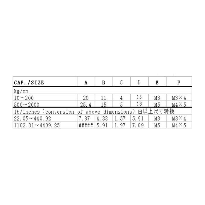
METRAVON MV-LC0066 is a miniature compression load cell for compact force fixtures, including button testing and space-limited assembly equipment. The documented range extends from 10 to 2000 kg, with a change in mounting geometry between the listed groups. Its nominal sensitivity is 1 mV/V rather than the 2 mV/V used by many other force sensors. Both the support drawing and acquisition channel therefore matter when replacing a small round cell.
Check the miniature compression load cell fixing pattern
The 10-200 kg dimensional group gives a 20 mm body diameter, 11 mm overall height reference and a 15 mm fixing circle. Its top thread is M3, with three M3 x 4 fixing references at 120 degrees. For the 500-2000 kg group, body diameter becomes 25.4 mm, height 15 mm and fixing circle 18 mm; the top thread is M5 and the three fixing references are M4 x 5. Those thread entries need the released depth and engagement definition, not an assumption that any screw length is acceptable.
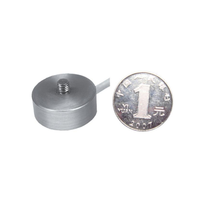
Treat the top stud as part of a compression arrangement
The upper projection references are 4 mm for the smaller group and 5 mm for the larger group. Obtain the approved mating contact and holding method so that tightening a fitting does not twist the sensing body. The model description specifies compression; an upper thread and lower fixing holes do not establish a tension-measurement specification. Show the support face, surrounding pocket and moving tooling in section. Keep adjacent fixture parts from becoming unintended contacts on the body.
Set the reader for the 1 mV/V bridge
Rated output is 1.0 +/-0.015 mV/V at 10-12 V DC excitation. Input resistance is 750 +/-20 ohms and output resistance is 700 +/-5 ohms. A channel retained from a nominal 2 mV/V cell needs its gain, span and useful force resolution reviewed rather than only its display zero reset. If the controller accepts 4-20 mA, include a bridge-compatible external conditioner in the channel design; no native current output or digital protocol is established by this model entry. Confirm delivered wiring and compression sign before scaling.
| Item | Value | Selection notes |
|---|---|---|
| 10-200 kg body / height | 20 / 11 mm | Fixing-circle reference: 15 mm. |
| 10-200 kg top / fixing threads | M3 / three M3 x 4 | The fixing positions are spaced at 120 degrees. |
| 500-2000 kg body / height | 25.4 / 15 mm | Fixing-circle reference: 18 mm. |
| 500-2000 kg top / fixing threads | M5 / three M4 x 5 | Use the rated drawing for depth and usable engagement. |
| Rated bridge output | 1.0 +/-0.015 mV/V | Do not retain a 2 mV/V span setting without recalibration. |
| Input / output resistance | 750 / 700 ohms | Respective tolerances are +/-20 and +/-5 ohms. |
| Enclosure entry | IP66 | The lateral exit and external termination need exposure review. |
Select useful force points, not the largest miniature rating
Give the preload, process interval and smallest force difference used to make a pass/fail decision. The available table labels precision as 0.05% FS and temperature effect as 0.05% FS per 10 deg C. These values do not mean 0.05% of a small button force on a much larger rated sensor. Check the completed fixture at its decision points with the production contact fitted. Neither the compact dimensions nor the listed applications supplies a response-time or robot safety rating.
Reserve room for the lateral cable and maintenance access
The cable leaves from the side near the lower part of the body; its route must clear the fixture and remain free of moving tooling. Allow access to the three fixing positions and avoid a pocket that traps or pulls the cable. The enclosure entry is IP66, with -40 to +85 deg C operation. It does not establish an immersion rating or resistance to every process fluid. The 200% FS safe-load limit is not an approved repeated overload cycle for the small threaded connections.
For a taller cylindrical body with a cable route beneath the base, compare the MV-LC0068 bottom-exit compression arrangement. Its 1-5 t family and 2 mV/V bridge require a different capacity, support and channel review.
Small fixing threads and a different bridge span
Q1. Can the same base serve a 100 kg and a 1000 kg cell?
The listed groups have different body diameters, fixing circles and thread sizes. Compare the actual rated drawings before sharing a fixture base. Do not enlarge one fixing pattern and assume the support conditions remain acceptable.
Q2. Why is the reading wrong after changing from a 2 mV/V cell?
The new nominal full-range signal is different at the same excitation. Check the reader input configuration and calibrate the working force points with the delivered unit. Mechanical preload or a wrong force rating must also be excluded before changing gain.
Q3. Is the upper threaded connection suitable for pulling?
The available description establishes compression loading only. If the fixture needs tension or reversal, request a specifically supported model and calibration arrangement. A retaining thread is not evidence of tensile measurement approval.
