


 Chinese
 Spanish
 Russian
 Portuguese
 French
 German
 Indonesian
 Thai
 Vietnamese
 Arabic
 Italian
 Turkish
 Polish
 Japanese


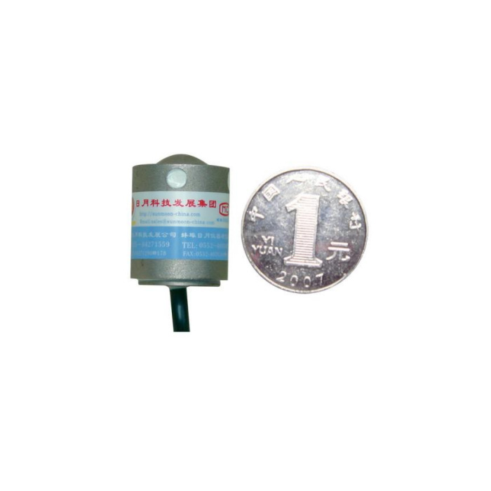

METRAVON MV-LC0068 is a miniature compression load cell with a spherical upper contact and a cable exiting beneath the cylindrical body. The 1-5 t technical family can be considered for compact force fixtures only when the support leaves a protected lower cable route. A round body that fits the available diameter may still be unsuitable if its cable is trapped against the base. The upper contact, lower support and wiring clearance should be reviewed in one section drawing.
Plan the lower cable route before locating the miniature compression load cell
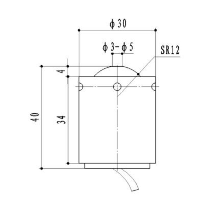
The reference drawing gives a 30 mm body diameter, a 34 mm body-height reference and a 40 mm overall reference including the end features. The free cable below the body needs additional room; 40 mm is not a complete installed-height allowance. Show the base opening or cable channel and how the cable is restrained away from the load-bearing contact. Do not allow the exit hardware to carry the measured force, and do not assume a through-hole support is approved without reviewing the required bearing area.
Keep the spherical contact free of surrounding tooling
The upper dome carries an SR12 profile and a 4 mm rise reference. Align the opposing member with that intended compression contact rather than supporting the tool on the surrounding top edge. Show any pocket or retaining feature and the clearances through the expected motion. The outline also contains side-hole annotations without a complete mounting definition. Obtain their purpose and the actual support detail instead of treating them as confirmed fixing threads or a licence to clamp the body.
| Item | Value | Selection notes |
|---|---|---|
| Technical compression family | 1-5 t | Confirm the actual rating and useful process force points. |
| Body diameter | 30 mm reference | Allow for the support and any retention parts separately. |
| Body / overall height references | 34 / 40 mm | Free cable beneath the lower exit needs additional space. |
| Spherical contact / rise | SR12 / 4 mm | Match the top member to the intended force contact. |
| Input / output resistance | 380 / 350 ohms | Tolerances are +/-5 and +/-2 ohms respectively. |
| Enclosure entry | IP66 | Do not treat the lower cable route as an immersion-rated assembly. |
Use the bridge specification for this cylindrical version
The electrical entries are 2.0 +/-0.015 mV/V, 10-12 V DC excitation, 380 +/-5 ohms input and 350 +/-2 ohms output resistance. These are not the 1 mV/V and 750/700-ohm figures of the low-profile MV-LC0066. Compare both the excitation load and useful measurement span when changing sensor shapes. Resolve the delivered terminal identification and compression sign using the unit record; contradictory signal-colour references should not be turned into a connection instruction.
Agree force acceptance with the final base and contact
Specify working compression, preload, credible peak load and the reference forces needed to accept the process. The 0.05% FS precision entry describes a full-scale basis rather than the same percentage at every low reading. Compare repeated force points and unloading return with the actual top member, lower support and secured cable. If moving the cable changes zero, review the mechanical route before correcting the display. The reference does not supply an allowable side-force value or a data-acquisition sample rate.
Protect the lower exit without creating a second support
Use a cable guard that stays clear of the loaded body and avoids trapping debris against the base. The listed IP66 enclosure and -40 to +85 deg C range do not establish immersion or process-fluid compatibility. Confirm the cable termination and external conditioner location for the actual exposure. A 200% FS safe-load entry does not provide the strength rating for a proposed retaining collar, guard or support opening.
If the base cannot provide a lower cable route, assess the MV-LC0066 low-profile side-exit arrangement. It uses capacity-dependent fixing threads and a nominal 1 mV/V output, so it is not a cable-only replacement.
Lower cable clearance and the support face
Q1. Will the sensor and cable fit in a 40 mm-high cavity?
The overall drawing reference does not include the additional free cable route. Draw the base and exit clearance in section and confirm the support arrangement before approving the cavity. A forced cable bend is not a valid way to recover missing height.
Q2. Can the small side holes be used to hold the force fixture?
Their full function and attachment specification are not established by this outline. Request the rated mounting detail before assigning them a retaining or load-bearing role. Do not assume a hole is threaded or suitable for a clamp screw.
Q3. What should be checked if zero changes when the cable is secured?
Inspect whether the cable or exit fitting bears against the support or pulls on the body. Repeat the unloaded return and working force references after the route is corrected. Zero adjustment alone does not demonstrate that the contact and base are mechanically sound.
