


 Chinese
 Spanish
 Russian
 Portuguese
 French
 German
 Indonesian
 Thai
 Vietnamese
 Arabic
 Italian
 Turkish
 Polish
 Japanese


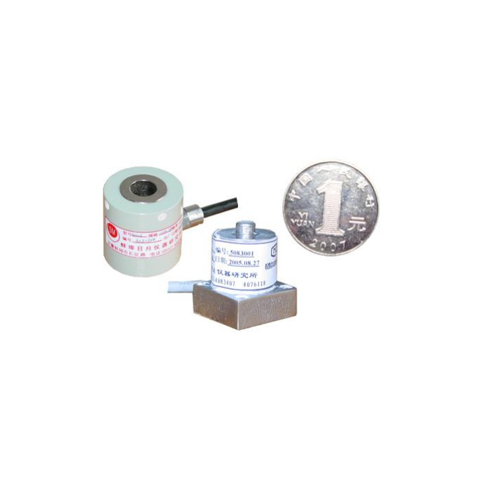

METRAVON MV-LC0069 is a square-base miniature compression load cell for a concentrated force contact in a restricted fixture. Its reference drawing shows a 20 x 20 mm base and 25 mm overall height, while the technical range is 1-3 t. The small mounting footprint does not establish low-force performance. Review the working force points, the contact member and the delivered rated drawing before committing the base plate.
Keep the miniature compression load cell contact distinct from its fixing base
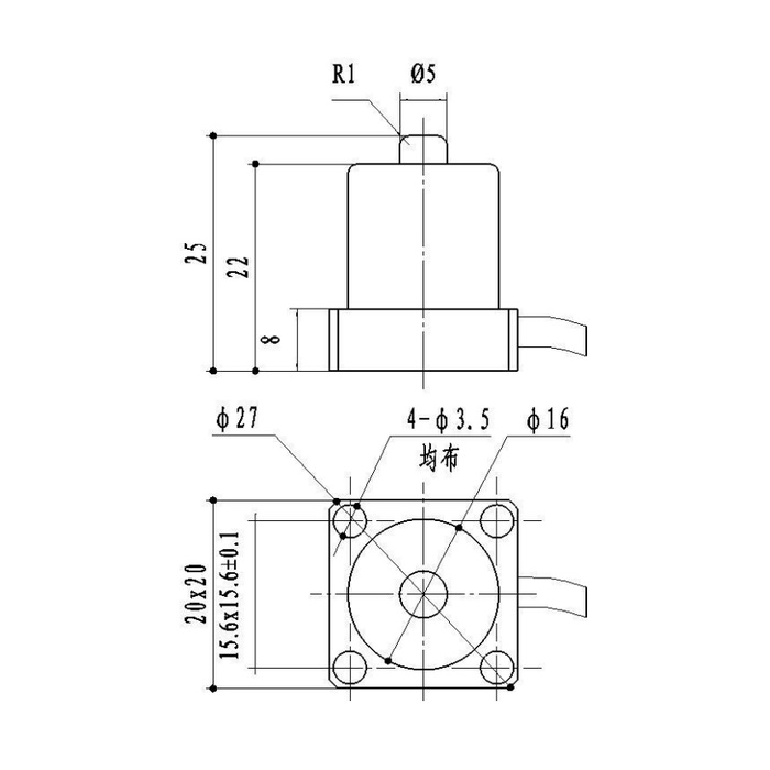
The axial contact is shown as a 5 mm diameter projection with an R1 edge reference. The drawing gives 22 mm to the body top, 25 mm overall and an 8 mm base-height reference. Introduce the measured compression through the intended top contact, with the base supported as specified for the unit. Do not let the actuator shoulder or a protective plate rest on the surrounding body. That extra contact can divert force without producing an obvious assembly fault.
Resolve the small fixing pattern before machining
The square view includes four diameter-3.5 hole references and a 15.6 x 15.6 mm spacing reference with a 0.1 mm tolerance. It also contains circular callouts that need to be read with the correct physical version. Request the complete toleranced mounting view and fastener requirements rather than assigning a purpose to every circle in the reference image. Include clearance for the lateral cable and any tool access; a 20 mm square in plan is not the whole installed envelope.
| Item | Value | Selection notes |
|---|---|---|
| Technical force family | 1-3 t | Confirm the actual rating; the compact package does not define low-force suitability. |
| Square base / overall height | 20 x 20 / 25 mm | The lateral cable and its protection need additional space. |
| Body-top / base-height references | 22 / 8 mm | Use the released drawing for the physical version being ordered. |
| Raised contact / edge reference | 5 mm / R1 | This is an axial force contact, not a specified pressure-sensitive area. |
| Four fixing holes | 3.5 mm diameter reference | Confirm the 15.6 x 15.6 mm pattern, tolerances and fasteners. |
| Bridge input / output resistance | 380 / 350 ohms | The listed tolerances are +/-5 and +/-2 ohms respectively. |
Specify force acceptance instead of a nominal pressure reading
The sensor measures compression force. Its 5 mm contact label is not a pressure-measurement range or proof of the contact area under load. If the process specification is expressed as pressure, identify the actual loaded area and the engineering relationship used by the equipment. For a force test, state the useful force interval and allowable result at its decision points. The listed precision is 0.05% FS, not the same percentage of every small reading, and no lateral-load accuracy or force-recording bandwidth is specified.
Verify the bridge and reference loads in the completed fixture
The electrical data is 2.0 +/-0.015 mV/V at 10-12 V DC excitation, with 380 +/-5 ohms input and 350 +/-2 ohms output resistance. Select the bridge reader and any downstream converter for those values. Establish the delivered terminal identification and compression sign before setting engineering units; the available colour legend and circuit disagree on the signal pair. Apply agreed reference forces through the final contact and check repeat loading and return. IP66, -40 to +85 deg C and the 200% FS safe-load entry do not establish immersion suitability, tooling performance or a routine overload cycle.
Concentrated force and a small mounting footprint
Q1. Can the 5 mm projection be used to calculate process pressure directly?
Not from that diameter alone. The force-to-pressure relationship depends on the actual contact or loaded area and the equipment arrangement. Keep the force calibration separate from any area calculation and validate the process quantity that is actually required.
Q2. Will a fixture pocket around the cylindrical body improve the measurement?
It may introduce unwanted side contact or restrain the sensing body. Submit the proposed pocket, support and axial contact in section before deciding how the unit is located. A close-fitting body pocket is not a substitute for the approved base arrangement.
Q3. What information makes an enquiry usable for this small base?
Provide the actuator-contact section, base-hole layout, available height and cable clearance, together with working and maximum compression. Include the bridge reader and required force checks. Ask for the rated drawing and fastener definition rather than approving the assembly from the reference photograph.
