


 Chinese
 Spanish
 Russian
 Portuguese
 French
 German
 Indonesian
 Thai
 Vietnamese
 Arabic
 Italian
 Turkish
 Polish
 Japanese


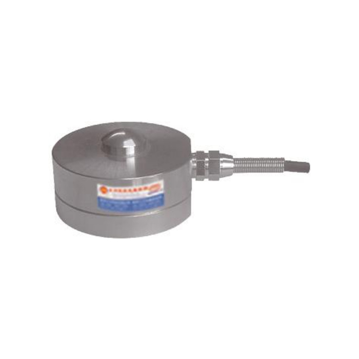

METRAVON MV-LC0070 is a compression button load cell with a locating recess in its lower face and a cable exiting from the side. The 1-3 t technical family uses a 2 mV/V bridge, but its resistance differs from several other compact compression sensors. Selection should identify how the base is supported and located, how the button contacts the loading member, and which reader will power the actual bridge.
Do not treat the locating recess as a threaded attachment
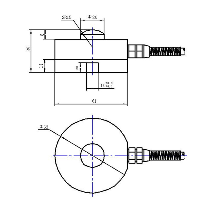
The lower feature is shown as a nominal 10 mm recess with positive dimensional allowances and an 8 mm depth reference. The drawing does not label it as M10. Obtain the permitted locating fit and depth before making a pin, and confirm that the base support remains in the intended contact. A locating pin must not bottom out or become an undocumented force-transfer feature. No thread engagement, fastener torque or tensile attachment is established by this recess label.
Check the compression button load cell envelope in both views
The top view gives a 63 mm diameter reference, while the side view carries a 61 mm span. Overall height is 36 mm, and the upper contact has a 20 mm diameter reference, SR15 spherical profile and 8 mm height reference. Use a confirmed drawing to resolve the complete outer profile before cutting a close pocket. Allow for the lateral cable gland, strain relief and the mating platen, not only the nominal body diameter and sensor height.
Match the 700-ohm output bridge to the acquisition channel
Input resistance is 750 +/-5 ohms and output resistance is 700 +/-2 ohms. The documented supply is 10-12 V DC excitation, and rated output is 2.0 +/-0.015 mV/V. A neighbouring sensor with the same sensitivity may have a different excitation load or require different reader checks. If the fixture combines several channels, state how each bridge is powered and calibrated. Do not parallel dissimilar sensors or reuse trim settings merely because the nominal mV/V figure agrees.
| Item | Value | Selection notes |
|---|---|---|
| Capacity family | 1-3 t | Confirm the selected rating and full installation drawing. |
| Lower locating recess | 10 mm nominal / 8 mm depth | Positive diameter allowances are shown; this is not an M10 thread callout. |
| Top contact | 20 mm / SR15 | Check its 8 mm height reference with the mating platen. |
| Overall height | 36 mm | Add the cable and surrounding fixture clearances separately. |
| Top-view diameter / side span | 63 / 61 mm references | Resolve the full profile on the confirmed drawing before machining. |
| Input / output resistance | 750 / 700 ohms | Listed tolerances are +/-5 and +/-2 ohms, not generic bridge tolerances. |
Make the contact and reference procedure part of the fixture offer
Show the top platen, locating recess, support face and lateral cable in a section through the force axis. Specify preload, useful compression and the reference points needed to decide whether the process passes. The listed precision is 0.05% FS and temperature effect is 0.05% FS per 10 deg C. Those entries do not include a binding locator, changed contact or unknown fixture compliance. Compare the completed fixture through loading and unloading with its production contact parts installed.
Confirm enclosure and wiring for the delivered configuration
The specification lists IP67 and -40 to +85 deg C, but does not define every connector, external conditioner or process-fluid exposure. Identify the termination and reader location on the quotation. Obtain the delivered wire functions because the reference signal-colour legend and circuit sketch disagree. Establish compression sign with an appropriate reference before accepting a span adjustment. The 200% FS safe-load entry is not a planned test percentage or an assurance for repeated press impacts.
If the fixture cannot accommodate a lateral gland, review the MV-LC0071 axial-exit arrangement. It needs lower clearance and a different body and bridge check, so it is not a cable-only substitution.
Locating fit and bridge matching
Q1. Can an M10 screw be fitted into the bottom feature?
The reference describes a dimensioned recess, not a threaded M10 hole. Confirm its actual function and fit with the delivered drawing. Do not force a screw into the feature or assume that it provides tensile retention.
Q2. Will the existing 350-ohm bridge settings work unchanged?
Review them against this 750-ohm input and 700-ohm output specification. The nominal sensitivity alone cannot confirm the reader configuration, excitation load or trim method. Re-establish the force references after the physical and electrical arrangements are accepted.
Q3. What should be checked if the empty reading changes after assembly?
First review whether the locator bottoms out, the cable pulls on the body or the platen touches anything beyond the intended button. Use the approved inspection method before adjusting zero. Repeated reference loads are needed to confirm the installed response, not only the empty display.
