


 Chinese
 Spanish
 Russian
 Portuguese
 French
 German
 Indonesian
 Thai
 Vietnamese
 Arabic
 Italian
 Turkish
 Polish
 Japanese


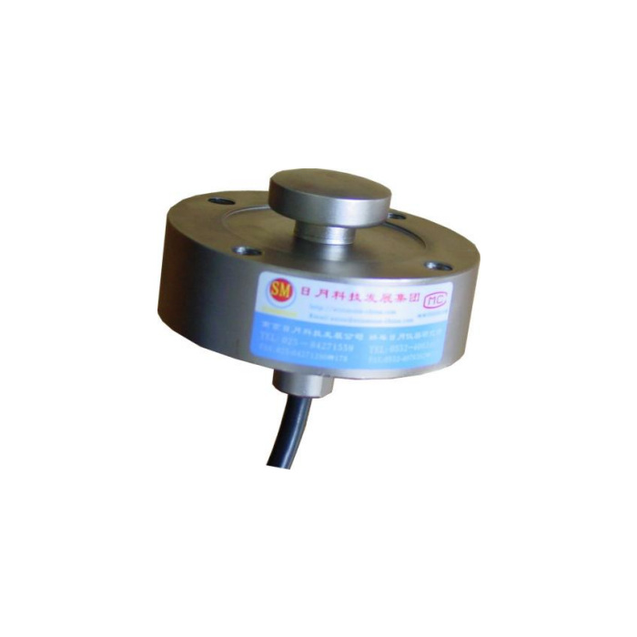

METRAVON MV-LC0071 is a compression load cell with an axial cable exit below the body. This arrangement can suit a fixture where a lateral cable would foul nearby tooling, but it needs a clear route through or around the support. The documented family is 1-5 t. Approve the lower exit space and the bearing contact before treating the circular body diameter as the complete installation envelope.
Leave space beneath the axial cable exit
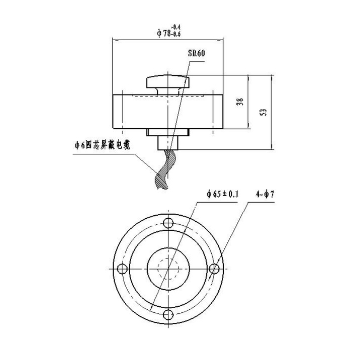
The side view shows height references of 38 and 53 mm, with the longer reference including the lower exit hardware. Neither value specifies the additional free cable length or bend allowance needed by the fixture. Show the support section, lower opening and strain relief in the enquiry. A plate that traps the exit fitting can preload the body or damage the cable even if the sensor sits flat during an initial unloaded trial. Do not modify the fitting to recover space without an approved arrangement.
Locate the compression load cell without loading its surrounding face
The nominal outer-diameter reference is 78 mm with its own drawing tolerance, and the four diameter-7 mounting holes are on a 65 +/-0.1 mm circle. The upper compression contact has an SR60 reference. Match the top member to that intended contact and confirm the load-bearing support and fasteners for the actual rated unit. The outer circular face and the cable fitting are not alternative points for applying the measured compression.
| Item | Value | Selection notes |
|---|---|---|
| Technical family | 1-5 t | Tie the selected rating to the installed fixture requirements. |
| Upper / lower height references | 38 / 53 mm | Reserve additional free cable and strain-relief clearance. |
| Body-diameter reference | 78 mm nominal | Use its full tolerance on the released drawing. |
| Mounting circle / holes | 65 +/-0.1 mm / four 7 mm holes | Confirm the complete fastener and supporting-face arrangement. |
| Compression contact profile | SR60 | The surrounding face is not an additional loading platen. |
| Bridge input / output | 380 / 350 ohms | Input tolerance is +/-5 and output tolerance +/-2 ohms. |
| Enclosure entry | IP67 | The support opening, termination and reader need their own exposure review. |
Check the actual channel when changing the cable route
The specified bridge is 2.0 +/-0.015 mV/V at 10-12 V DC excitation, with 380 +/-5 ohms input resistance and 350 +/-2 ohms output resistance. Changing from a side-exit sensor can therefore involve a bridge change as well as a mechanical one. Compare the delivered unit, reader excitation and engineering-unit calibration rather than moving only the cable connection. Use confirmed wire identification and a controlled compression sign check; do not select polarity from contradictory colour references.
Accept the fixture with its final cable restraint
Agree force references near the actual process decision points, then compare repeated compression and return after unloading with the cable secured as it will be used. Include any permitted motion of the fixture and check that it does not pull the lower exit or change the indicated zero. The listed precision is 0.05% FS; temperature effect is 0.05% FS per 10 deg C. No arbitrary eccentric-load allowance, sample rate or fatigue life can be derived from those entries.
Where no route is available beneath the support, the MV-LC0070 side-exit layout provides another geometry to assess. Its locating recess, capacity family and 750/700-ohm bridge need their own review before selection.
Lower-exit clearance and cable-induced load
Q1. Can the support plate sit directly against the lower cable fitting?
That is not a confirmed load-bearing feature. Show the exit hardware and required clearance in section and obtain the approved support arrangement. Do not let the fitting carry the measured force or use cable compression to retain the body.
Q2. Does an axial cable make the whole assembly only 38 mm high?
The drawing also carries a 53 mm lower-exit reference, and the free cable needs further space. Include the full route beneath the body and tool access when checking the envelope. The shorter height alone is not an installed-clearance specification.
Q3. What should be retested after a cable restraint is moved?
Check unloaded return and the agreed compression references with the new restraint and normal fixture motion. A stable bridge on the bench cannot rule out an installed cable force. Inspect the mechanical route before applying a software zero correction.
