


 Chinese
 Spanish
 Russian
 Portuguese
 French
 German
 Indonesian
 Thai
 Vietnamese
 Arabic
 Italian
 Turkish
 Polish
 Japanese


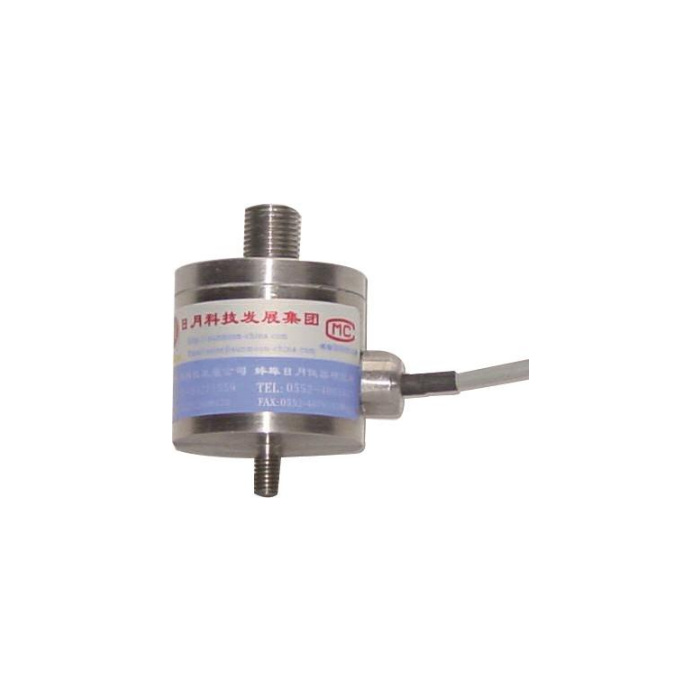

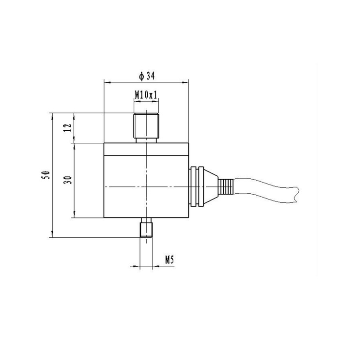
METRAVON MV-LC0072 is a threaded compression load cell documented for a 5-100 kg family. Its reference drawing identifies M10 x 1 at the upper end and M5 at the lower end, with a 34 mm body diameter. The unequal connections need separately matched fixture parts. Although the body has two studs, the available description specifies compression loading and does not establish a tensile or bidirectional measurement specification.
Match each end of the threaded compression load cell independently
The upper thread is explicitly M10 x 1, so nominal M10 alone is not a sufficient fitting description. The lower end is marked M5 without a pitch in the table. Confirm both mating connections, usable engagement and any locking arrangement on the delivered drawing. Do not make an adapter from a photograph, force a different M10 pitch onto the upper stud or use the cable to hold the body while tightening. No tightening torque is specified by these labels.
| Item | Value | Selection notes |
|---|---|---|
| Technical family / direction | 5-100 kg / compression | Tensile or reversed loading requires separate model-specific confirmation. |
| Upper connection | M10 x 1 | Check the full fine-pitch specification at the mating fitting. |
| Lower connection | M5 reference | Confirm the complete thread and usable engagement. |
| Body diameter / height | 34 / 30 mm | The complete end-to-end reference is 50 mm. |
| Upper projection reference | 12 mm | Do not substitute the visible projection for approved engagement. |
| Input / output resistance | 380 / 350 ohms | The respective tolerances are +/-5 and +/-2 ohms. |
Keep fixture adjustment from becoming an unwanted force input
The body-height reference is 30 mm and the end-to-end reference is 50 mm; the upper projection is shown as 12 mm. Usable thread engagement can be less than a visible projection, so obtain the actual connection requirement. Show how the two force members stay coaxial as the fixture moves and how the body is held during adjustment. A coupling that bottoms out or turns against an unintended shoulder can impose preload that is not part of the intended test.
Choose the useful compression range before retaining old display units
Provide the expected force interval, preload and the points used to accept the part or process. The 5-100 kg family label does not confirm every intermediate rated version or the suitability of a 100 kg unit for a much smaller reading. The precision entry is 0.05% FS, and temperature effect is 0.05% FS per 10 deg C. Define what the installed fixture must resolve at its actual working forces. Confirm the required force units explicitly if the control system reports newtons rather than the capacity units on the reference sheet.
Wire and scale the bridge for the delivered compression direction
The electrical channel is 2.0 +/-0.015 mV/V with 10-12 V DC excitation, 380 +/-5 ohms input and 350 +/-2 ohms output resistance. It needs a suitable bridge acquisition channel or an external conditioner for a PLC current input. Obtain the delivered terminal record, confirm force sign and set the engineering scale with controlled compression references. Reversing display sign does not establish a verified tensile calibration or make an unconfirmed loading direction acceptable.
Inspect the final threaded assembly before force acceptance
After the connections are approved, compare repeat force points, unloading return and any permitted adjustment sequence with the final cable routing. Check that guards and adjacent members stay clear throughout motion. IP67 and -40 to +85 deg C apply to the sensor entry, not automatically to rod ends, adapters or the reader. The 200% FS safe-load figure is not a rating for the M5 attachment or permission to perform repeated double-range tests.
Unequal threads and confirmed loading direction
Q1. Can it measure tension because it has a stud at each end?
That conclusion is not supported by the compression-only reference. Obtain an explicit tensile or bidirectional specification for the actual offered configuration if the fixture needs it. The presence of threads and a reversible display sign are not sufficient evidence.
Q2. Will an ordinary M10 adapter fit the top connection?
Only if its full thread matches M10 x 1 and the approved engagement. A nominal M10 label can refer to a different pitch. Confirm the lower M5 connection separately instead of ordering two identical fittings.
Q3. Why does tightening the connections change the unloaded reading?
An adapter that bottoms on an unintended shoulder or a constrained threaded joint can preload the cell. Check the approved engagement and force path with the fixture unloaded before adjusting the display. Then repeat the compression references with the final locking arrangement; zero adjustment alone cannot confirm the mechanics.
Q4. What details are needed for a fixture quotation?
Send both mating-end drawings, the compression interval and preload, required force units, available end-to-end space and the acquisition channel. Identify any reversal or repeated impact explicitly so that unconfirmed conditions are not included by assumption.
