


 Chinese
 Spanish
 Russian
 Portuguese
 French
 German
 Indonesian
 Thai
 Vietnamese
 Arabic
 Italian
 Turkish
 Polish
 Japanese



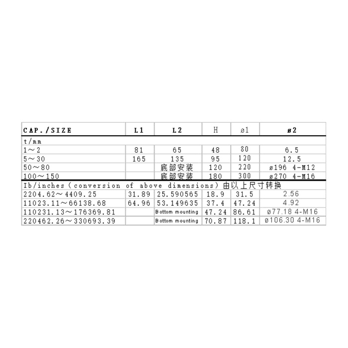
METRAVON MV-LC0073 is a compression load cell family whose mounting arrangement changes substantially with capacity. The reference spans 1-150 t: lower groups use a square flange layout, while higher groups are identified for bottom mounting. It should not be treated as one miniature envelope available at every rating. Choose the actual capacity and mounting group before quoting the base, mating contact or removal access.
Compare the lower-capacity compression load cell flange patterns
For 1-2 t, the metric table gives L1 81 mm, L2 65 mm, H48 mm, body-diameter reference 80 mm and a 6.5 mm fixing-hole reference. The 5-30 t group changes those values to 165, 135, 95, 120 and 12.5 mm respectively. Thus a larger rating can change both the base footprint and the support height. Use the exact rated drawing rather than enlarging holes in the original flange or assuming a spacer can make the two groups mechanically equivalent.
Treat the bottom-mounted groups as different base designs
The 50-80 t row gives H120 mm and a 220 mm body-diameter reference, with four M12 positions on a 196 mm circle. At 100-150 t, H becomes 180 mm, diameter 300 mm and the bottom references become four M16 positions on a 270 mm circle. The table identifies these as bottom mounting rather than supplying the earlier square L1/L2 layout. Obtain the underside detail, thread definition and usable engagement before making the base, including how the sensor can be installed or removed.
| Item | Value | Selection notes |
|---|---|---|
| 1-2 t L1 / L2 / H | 81 / 65 / 48 mm | Body diameter is 80 mm and fixing-hole reference 6.5 mm. |
| 5-30 t L1 / L2 / H | 165 / 135 / 95 mm | Body diameter is 120 mm and fixing-hole reference 12.5 mm. |
| 50-80 t H / diameter | 120 / 220 mm | Bottom reference: four M12 positions on a 196 mm circle. |
| 100-150 t H / diameter | 180 / 300 mm | Bottom reference: four M16 positions on a 270 mm circle. |
| Bridge input / output | 775 / 700 ohms | Tolerances are +/-5 and +/-2 ohms respectively. |
| Enclosure entry | IP66 | Confirm the exact cable termination and any site-specific enclosure needs. |
Use the 775-ohm input figure rather than a neighbouring bridge value
Rated output is 2.0 +/-0.015 mV/V with 10-12 V DC excitation. Input resistance is listed as 775 +/-5 ohms and output as 700 +/-2 ohms. Do not replace the input value with a familiar 750-ohm entry from another sensor or assume identical trim settings. For a replacement in a multi-support system, provide the other cells and reader arrangement so the actual excitation load and calibration can be reviewed. Delivered wiring identification is required where the available colour references disagree.
Size the support reaction and useful measured interval together
Include permanent attachments and preload when they act through the sensor, and determine the greatest individual support reaction for the real loading conditions. A nominal total divided by the number of supports is not sufficient where load distribution varies. The precision entry is 0.05% FS; it does not determine the finished scale result at small inventory changes or under an unspecified contact arrangement. State reference loads and allowable installed results at the points that matter to the project.
Confirm protection and acceptance for the selected physical version
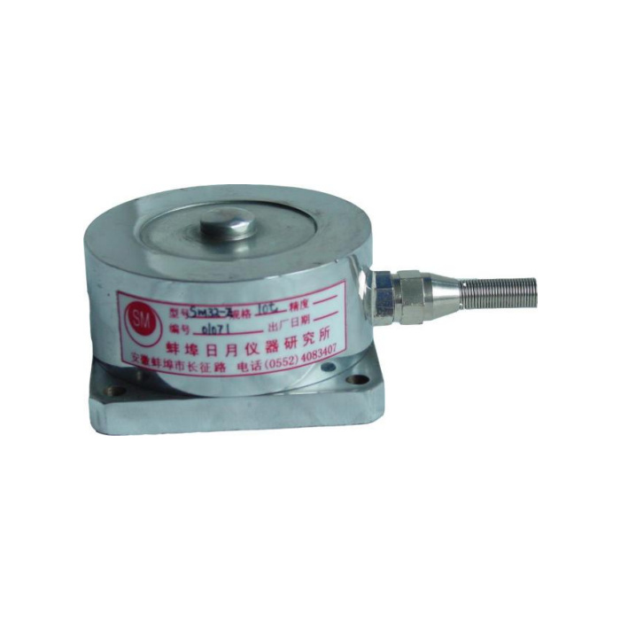
The specification lists IP66, not an automatic immersion rating, with -40 to +85 deg C operation. Check the cable termination, external enclosure and maintenance exposure separately. The reference photograph illustrates a small body and does not identify every high-capacity mounting version. Ask the offer to include the selected rated drawing, contact requirements and supplied hardware. Verify repeated compression and unloaded return with that final arrangement; do not interpret the 200% FS safe-load entry as a general commissioning test load.
Capacity groups, bases and retained scale channels
Q1. Can the square flange layout be retained for a 100 t replacement?
The 100-150 t reference group is bottom mounted, with a 300 mm body and a different fixing arrangement. Do not transfer the lower-capacity square layout to that body. Obtain the matched underside drawing and review the base and removal access.
Q2. Does the 1-150 t family confirm every intermediate rating?
It gives an overall technical range and grouped dimensional references, not a supply commitment for arbitrary ratings. State the required capacity and request its own matched configuration. Keep any range gaps or unlisted versions as confirmation items.
Q3. Is the existing bridge input necessarily the same because both outputs are 2 mV/V?
No. This model lists a 775-ohm input, and another cell may use a different value. Check the actual reader, connected cells and delivered sensitivity. Re-establish the useful load references after the physical support arrangement is approved.
