


 Chinese
 Spanish
 Russian
 Portuguese
 French
 German
 Indonesian
 Thai
 Vietnamese
 Arabic
 Italian
 Turkish
 Polish
 Japanese


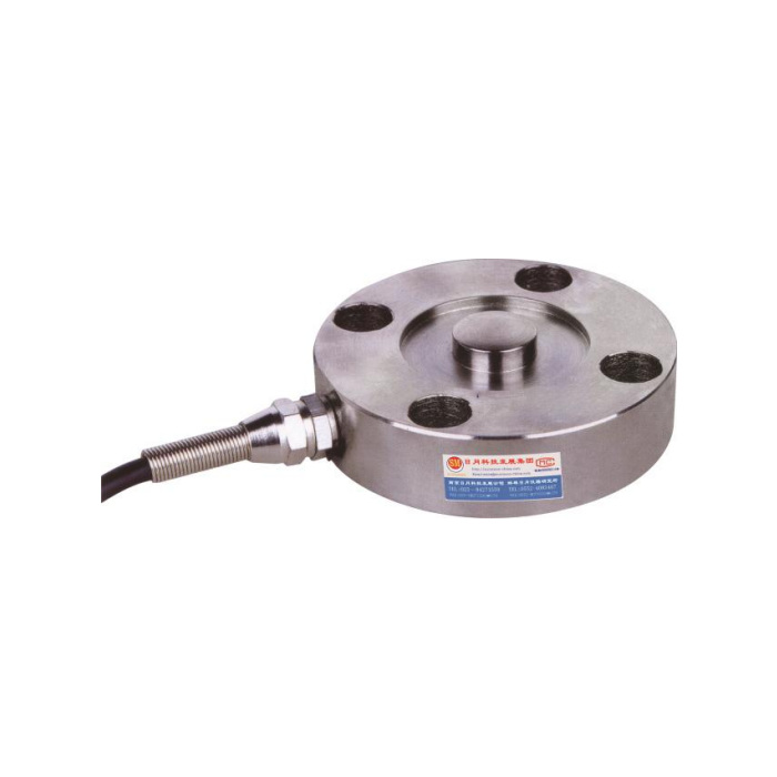

METRAVON MV-LC0074 is a low-profile compression load cell for force measurement where fixture height is restricted. The documented family is 1-5 t, with a raised central load button on an 86 mm diameter body. Its compact shape should not be confused with a sensor intended for very small forces. Select the actual rating against the useful compressive force interval before designing the platen and mounting around the outline.
Bring compression onto the raised load button
The drawing gives a 20 mm button reference with an SR50 spherical profile. Body height is 22 mm and overall height to the button is 26 mm. The mating platen must introduce the intended force through that contact without also resting on the surrounding top face. Show the loading member, support face and any guidance in section. A rigid guard or platen that bears on the body rim can divert force away from the measuring contact even when the fixture appears to close squarely.
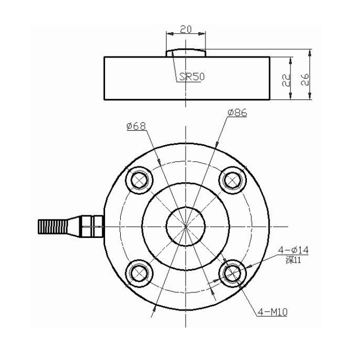
Check the low-profile compression load cell fixings and cable space
The outline shows an 86 mm outer diameter, a 68 mm fixing-circle reference, four M10 references and four diameter-14 counterbore references marked 11 mm deep. Obtain the delivered mounting definition, usable thread engagement and fastener requirements before machining. Do not infer a tightening torque or an interchangeable bolt kit from those labels. Include the side cable exit and its strain relief when checking the available envelope; the circular body diameter is not the complete installed width.
| Item | Value | Selection notes |
|---|---|---|
| Nominal family | 1-5 t | Match useful force points to the selected full scale. |
| Body diameter / overall height | 86 / 26 mm | The cylindrical body itself is 22 mm high. |
| Load-button reference | 20 mm / SR50 | Preserve the intended central contact with the mating platen. |
| Fixing-circle reference | 68 mm | Confirm the complete delivered hole and thread definition. |
| Input / output resistance | 380 / 350 ohms | Listed tolerances are +/-5 and +/-2 ohms. |
| Rated output / excitation | 2.0 mV/V / 10-12 V DC | The sensitivity tolerance is +/-0.015 mV/V. |
Compare the process decision forces with the chosen full scale
The listed precision is 0.05% FS and the temperature-effect entry is 0.05% FS per 10 deg C. A full-scale-related figure is not a percentage of every small force reading. For a press or assembly test, specify the force points that determine acceptance, any preload and the highest intended compression. Do not select a tonne-range sensor for a light-force test merely because the same general application appears in a family description. No bandwidth, cycle life or lateral-force accuracy is established here.
Set the bridge channel before accepting a force trace
The electrical entry is 2.0 +/-0.015 mV/V at 10-12 V DC excitation, with 380 +/-5 ohms input and 350 +/-2 ohms output resistance. A compatible bridge reader must provide excitation, amplification and calibration. Where a PLC records 4-20 mA, identify the separate conditioner and the force values assigned to that output. Use the delivered wiring record and a controlled compression reference to confirm sign; the reference colour legend and circuit sketch disagree on the signal pair.
Test with the production contact and support arrangement
Apply the agreed reference forces through the final button contact and compare repeated loading, unloading and zero return. If the platen position can vary, include the actual permitted positions in the fixture assessment instead of assuming unlimited eccentric loading. The listed 200% FS safe-load limit is not permission for routine double-capacity press cycles. IP67 and -40 to +85 deg C refer to the sensor entry; assess cable termination, tooling and local press temperatures for the actual installation.
Button contact and useful force range
Q1. Can the flat top face be loaded instead of the button?
The documented compression contact is the raised button. A platen touching the surrounding face changes the force path. Submit the proposed contact section for review rather than flattening, covering or bypassing the button.
Q2. Does miniature mean it is suitable for a small push-button test?
It describes the compact package, not an assured low-force range. This technical family is 1-5 t. Compare the required forces and allowable error with the actual rating before using it for a light-force test.
Q3. What should be supplied with a press-fixture enquiry?
Send a section through the platen, button and support, the available height, mounting pattern and cable exit, together with useful and maximum compression. Include the reader and required force-recording method. These details allow the mechanical contact and measurement channel to be checked together.
