


 Chinese
 Spanish
 Russian
 Portuguese
 French
 German
 Indonesian
 Thai
 Vietnamese
 Arabic
 Italian
 Turkish
 Polish
 Japanese



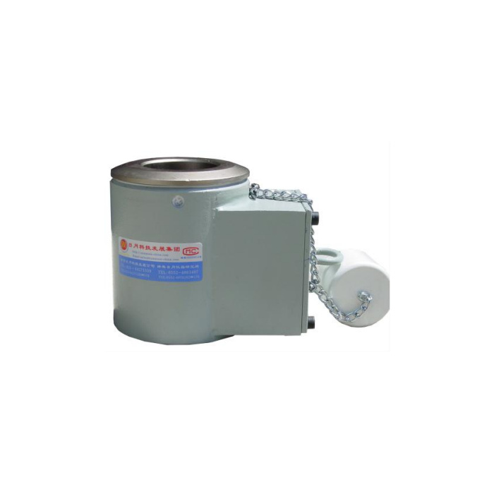
METRAVON MV-LC0075 is a through-hole load cell documented for pumping-unit load measurement, including polished-rod load and load-displacement recording. It is not simply a generic solid compression column. The force table lists 0-250 kN, while the outline table covers a 1-15 t body reference. Confirm the ordered force rating and matching bore dimensions together rather than treating those two entries as a complete specification for every version.
Match the pumping unit load cell to the actual load-bearing stack
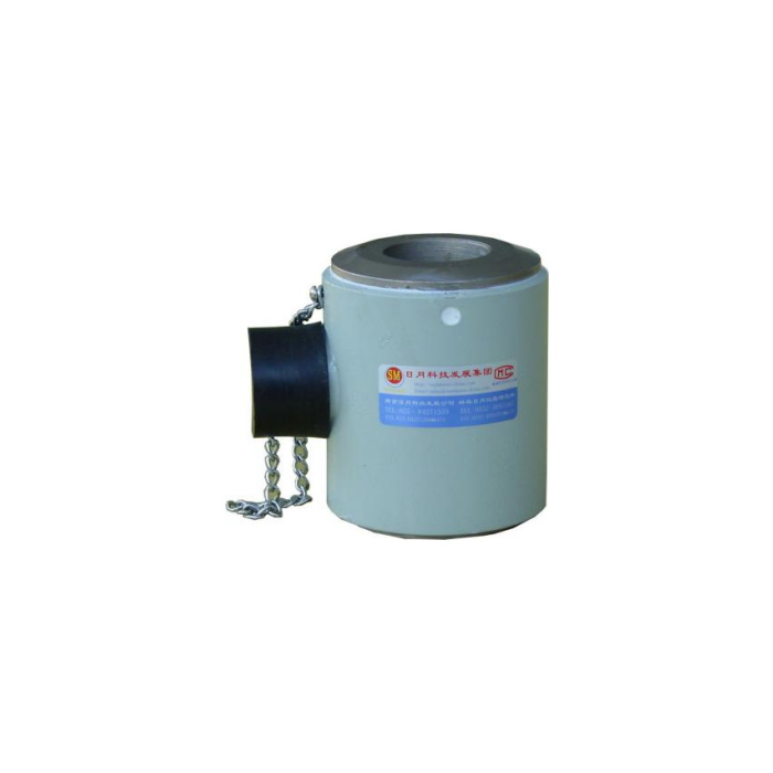
The outline uses bore A values of 30, 35, 40 and 50 mm, with H90 mm in its stated body group. Corresponding W/B references are 95/64, 106/74, 106/74 and 112/81 mm. Identify the rod diameter, required clearance, contact faces and available connector space from the approved equipment arrangement. A bore that clears the rod does not by itself establish suitable load transfer. Do not assume that the illustrated closed body can be fitted around an installed rod without the required disassembly.
Keep the 1 mV/V bridge separate from conditioned or wireless versions
The base electrical data gives 1.0 +/-0.05 mV/V sensitivity at 10 V DC, with input and output impedance entries of 730 +/-5 and 700 +/-1. At nominal sensitivity and 10 V excitation, rated bridge output is 10 mV, a calculated reference for reader selection. Do not retain a 2 mV/V full-scale setting from another load cell. Family references to current, voltage or external wireless equipment do not confirm those functions inside the offered unit; request the actual electrical version and connector documentation.
| Item | Value | Selection notes |
|---|---|---|
| Force-table entry | 0-250 kN | Confirm the actual rated version and matching through-hole body. |
| Outline-table scope | 1-15 t reference | Do not use this as dimensional approval for every force entry. |
| A30 / A35 W and B | 95/64 / 106/74 mm | Confirm the bore and contact geometry for the rod arrangement. |
| A40 / A50 W and B | 106/74 / 112/81 mm | H is 90 mm in the referenced outline group. |
| Bridge sensitivity / excitation | 1.0 mV/V / 10 V DC | Listed sensitivity tolerance is +/-0.05 mV/V. |
| Compensated / operating temperature | -10 to +65 / -40 to +85 deg C | Define the measurement requirement at the actual body temperature. |
| Safe-load entry | 150% FS | Not an approved test load or the working capacity of the rod assembly. |
Record load and position on a common measurement basis
A pumping-unit load-displacement record needs a suitable position source as well as this load channel. Specify the working force interval, stroke information, acquisition method and how the two records are associated. This sensor does not establish a built-in displacement output, sample rate or radio protocol. If an RTU or data logger is used, identify the bridge conditioner and the separately confirmed downstream signal. A force-only channel cannot supply the missing position information through software scaling.
Use compensated and operating temperatures for different decisions
The temperature-compensation entry is -10 to +65 deg C; operating temperature is -40 to +85 deg C. Those are not equivalent claims of measurement performance. State expected sensor-body temperature and the required load result over that interval. The precision entry is 0.5% FS, temperature effect is 0.5% FS per 10 deg C and the safe-load limit is 150% FS. Do not borrow the tighter precision, wider compensation or 200% limit of a nearby weighing model.
Define the installation and reference checks before field work
Provide the installed rod and support arrangement, exact rated requirement, mating connector and reader settings. Confirm the machine procedure for unloading, fitting and securing the sensing body before work starts. After the mechanical configuration is approved, establish the load scale with an appropriate reference method and check the recorded load-position relationship. A connector that mates or an apparently normal zero cannot prove that the correct sensitivity and rated body have been supplied. No hazardous-area certification is established by the IP67 entry.
Rated body, load-position records and field interfaces
Q1. Does the unit provide load and displacement together?
The documented base unit measures load. A load-displacement record needs a separately specified position channel and an acquisition arrangement that associates the two. Confirm any external transmitter and data format rather than inferring them from the sensor body.
Q2. Is the illustrated body confirmed for a 250 kN order?
That is not established by these references. Obtain the rated specification and drawing for the actual offered version, including bore, contact faces and connector. Keep the capacity units explicit on the quotation.
Q3. Can it connect directly to a 4-20 mA input?
Only if the supplied version is confirmed to provide that signal. The documented base unit is a millivolt bridge and needs a suitable conditioner for a current-input controller. Verify the actual output, excitation and pin identification rather than borrowing the specification of a related family version.
Q4. Does IP67 establish use in a classified oilfield area?
No hazardous-area approval follows from that enclosure entry. If the location requires such approval, obtain the applicable model-specific documents and assess the complete sensor, connector and acquisition arrangement before selection.
