


 Chinese
 Spanish
 Russian
 Portuguese
 French
 German
 Indonesian
 Thai
 Vietnamese
 Arabic
 Italian
 Turkish
 Polish
 Japanese



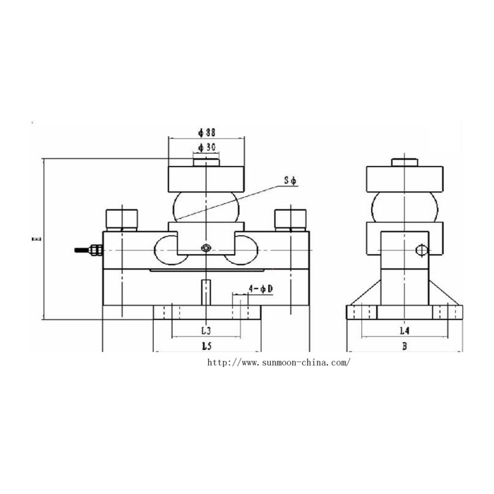
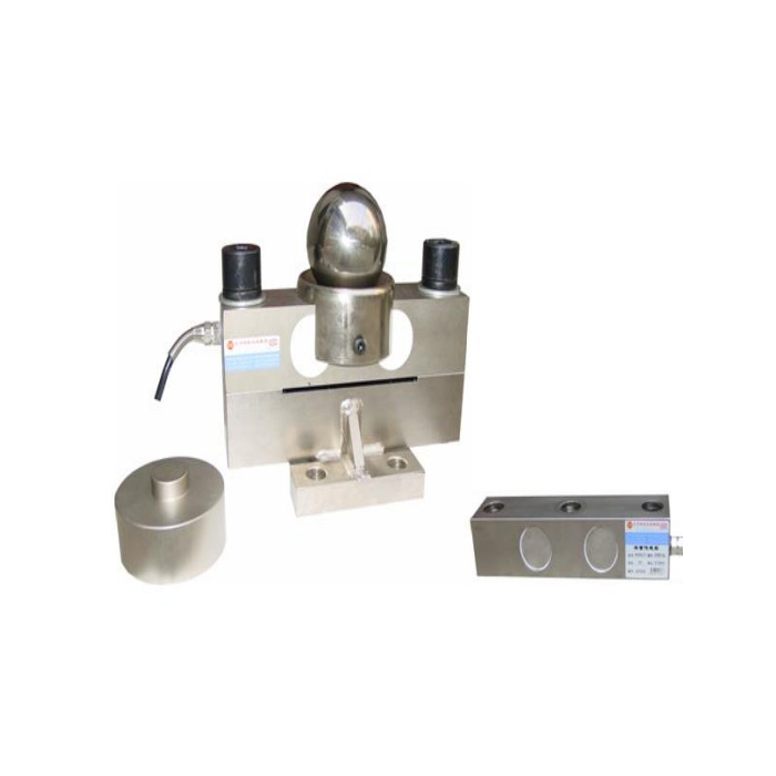
METRAVON MV-LC0076 is a ball-loaded bridge load cell for vehicle scales, rail scales, hoppers and other weighing supports. The described load-introduction assembly uses a loading head and steel ball. Its 10-50 t family changes height and contact geometry between capacity groups. For a repair or new support, identify the complete assembly rather than ordering only a bridge body with a similar output.
Compare the ball-loaded bridge assembly height before retaining the deck
The 10 t metric row gives H195 mm, while the 20-30 t group uses H225 mm. Both groups retain the listed L1 240 mm, B135 mm and diameter-18 fixing references, but the ball S reference changes from 50 to 76 mm. A matching footprint therefore does not preserve the support height or contact components. Check the deck clearance and the correct loading head and ball together; do not compensate for an unmatched assembly by adding arbitrary packing around the contact.
| Item | Value | Selection notes |
|---|---|---|
| 10 t H / ball S | 195 / 50 mm | Check the matched loading head and ball, not only the bridge body. |
| 20-30 t H / ball S | 225 / 76 mm | Smaller-group footprint references remain, but height and contact change. |
| 10-30 t L1 / B / fixing diameter | 240 / 135 / 18 mm | Full support and base dimensions still require the selected drawing. |
| 40-50 t H / ball S | 261 / 82 mm | This group also changes the base references. |
| 40-50 t L1 / B / fixing diameter | 340 / 160 / 21 mm | Review base steel, fasteners and adjacent restraints together. |
| Listed precision / temperature effect | 0.05% FS / 0.02% FS per 10 deg C | Agree the finished-scale result at actual reference loads. |
Include the larger base and contact set in a 40-50 t enquiry
The larger group uses H261 mm, L1 340 mm, B160 mm and diameter-21 fixing references, with ball S82 mm. Its L3/L4 references are both 124 mm, compared with 80/100 mm for the smaller groups. Use the dimension letters with this drawing and confirm the actual base and contact surfaces. Sharing the model family does not establish that retained bolts, loading heads or adjacent restraints are suitable for the larger support.
Keep the ball contact free to work within the approved support arrangement
Self-centring at the ball contact does not permit unrestricted movement or remove the need for scale restraints. Show the normal contact, horizontal restraint and any anti-lift provisions required by the equipment. Check for fouling by corrosion, debris or a displaced contact component before changing the bridge calibration. Replacing one contact part with a visually similar ball or cap can change the installed height and force transfer even when the unloaded signal remains plausible.
Match the electrical replacement to the complete scale channel
The rated output is 2.0 +/-0.01 mV/V at 10-12 V DC excitation. Listed input and output resistances are 750 +/-20 and 700 +/-5 ohms. Identify other connected cells, the junction box and the indicator setup before replacing a support. Obtain delivered wire identification and confirm loaded sign; do not decide polarity from the conflicting colour legend and circuit sketch. Restore the scale calibration with the final contact parts installed, not with a temporary loading arrangement.
Accept positional response as well as total indicated load
For the actual weighing equipment, agree reference loads, support positions and the required repeatability and zero-return checks. If a single support is changed, inspect the remaining contact sets and verify the relevant positional results. The 0.05% FS sensor precision entry is not an approval for the entire weighbridge or a regulated trade-weighing instrument. Define those system requirements separately. The 200% FS safe-load entry does not specify an allowable overload test for the installed scale.
For an installation with a curved saddle rather than a separate ball and head, compare the MV-LC0077 saddle-seat outline. Its capacity-unit records need confirmation, and the two contact arrangements are not interchangeable by bridge sensitivity alone.
Ball contacts and complete support replacements
Q1. Can the 10 t and 20 t versions share the existing load contacts?
Do not assume so. The listed ball reference increases from 50 to 76 mm and assembly height from 195 to 225 mm. Obtain the matched loading head, ball and support definition for the rated version before approving retained components.
Q2. Does the self-centring description make a side restraint unnecessary?
It does not define the equipment restraint requirement. Review the permitted movement, contact retention and surrounding scale structure. A restraint must control the intended motion without introducing an unintended measuring-force bypass.
Q3. What belongs on a replacement quotation besides the cell?
Identify the loading head, ball, base or fixing parts, cable termination and any required junction-box work separately. Attach the existing assembly views and rated requirement. This makes clear whether the offer replaces the complete support or only its sensing element.
