


 Chinese
 Spanish
 Russian
 Portuguese
 French
 German
 Indonesian
 Thai
 Vietnamese
 Arabic
 Italian
 Turkish
 Polish
 Japanese



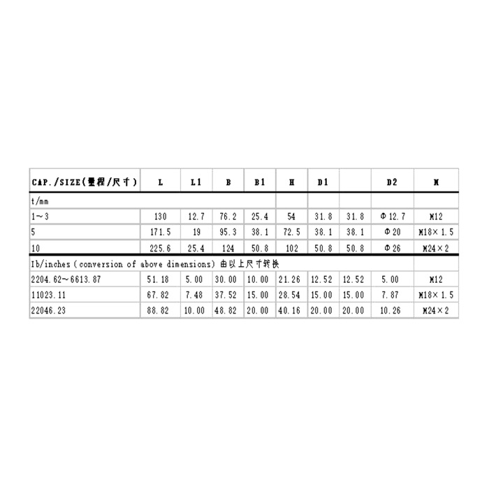
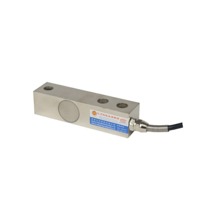
METRAVON MV-LC0059 is a cantilever load cell family for low-platform, forklift and hopper weighing arrangements. Its selection issue is not simply how many tonnes the beam can carry: the connection references and body envelope change with rating. The technical range begins at 0.1 t, but the dimensional groups supplied in the reference are 1-3 t, 5 t and 10 t. Keep the exact capacity and its drawing together when requesting the sensor and loading-head assembly.
Order the cantilever load cell connection for the selected capacity
The metric table lists an M12 connection reference for 1-3 t, M18 x 1.5 for 5 t and M24 x 2 for 10 t. It also gives overall length L as 130, 171.5 and 225.6 mm respectively. The M12 entry does not include an explicit pitch. Do not retain an old loading part on nominal diameter alone, or infer that the 5 t and 10 t fittings differ only in strength. Ask for the complete thread, engagement and approved contact parts on the delivered rated drawing.
Resolve the outline annotations before machining a support
The reference outline and its table do not use a fully consistent set of dimension headings. Some letter labels in the sketch are not repeated in the table, and the technical range includes lower capacities without matching rows. Treat that as a drawing-confirmation requirement, not a reason to reconstruct missing hole positions from the photo. Supply the existing support section and request a complete toleranced outline identifying the fixed end, load connection and cable exit. Use only an approved version for fabrication.
| Item | Value | Selection notes |
|---|---|---|
| Technical capacity range | 0.1-10 t | Lower-capacity dimensions are not supplied in the listed groups. |
| 1-3 t: L / connection reference | 130 mm / M12 | Pitch, engagement and full outline need confirmation. |
| 5 t: L / connection reference | 171.5 mm / M18 x 1.5 | Check the mating head and supporting envelope together. |
| 10 t: L / connection reference | 225.6 mm / M24 x 2 | Do not reuse a lower-rated attachment by appearance. |
| Precision entry | 0.05% FS | Agree useful process force or weight points separately. |
| Enclosure entry | IP67 | Specify the cable termination and actual site exposure. |
Keep the movable load head clear of guides and stops
The family description refers to a movable loading head. Show how that head meets the scale structure, what restrains lateral movement and whether the head can move through its permitted travel without rubbing. A guide or safety stop must not become an unnoticed parallel support during normal weighing. For a forklift arrangement, describe the attachment and load cases explicitly; the reference application list does not approve every truck or bracket. For a hopper, include pipe connections and vessel restraints in the same review.
Define the weight change the installed channel must resolve
Give dead load, maximum contents and the useful weighing interval at each support. The listed sensor precision is 0.05% FS and the temperature-effect entry is 0.02% FS per 10 deg C. These entries do not demonstrate that a higher-rated beam will measure a small batch increment with the required installed result. Agree reference loads and permissible readings around the actual batch or process decision points. For multiple supports, include likely changes in reaction rather than assuming a permanently equal load split.
Connect and accept the specific beam assembly
Rated output is 2.0 +/-0.001 mV/V at 10-12 V DC excitation. Bridge resistance is specified as 400 +/-20 ohms input and 350 +/-5 ohms output. Match the indicator or weight transmitter to that bridge and confirm the supplied terminal record; the reference colour list and circuit disagree on signal polarity. After the mechanics are accepted, verify loading, unloading return and any relevant support-position changes. IP67, -40 to +85 deg C and the 200% FS safe-load entry do not establish unlimited washdown exposure or a test load for the complete support.
Thread choices and incomplete dimension groups
Q1. Which drawing should be used for a 500 kg order?
Request the drawing for that exact offered capacity. The technical range includes it, but the listed dimension rows begin at 1-3 t. The larger row is not evidence that the 500 kg body and connections are identical.
Q2. Can an existing M12 loading part be retained?
Only after checking the complete thread and the approved load-head arrangement. The table does not state the M12 pitch or usable engagement. Retaining a part because it starts to screw in is not an adequate fit or load-path check.
Q3. What if a dimension letter in the table does not match the sketch?
Obtain a corrected, complete rated drawing before machining. Do not assign the value to whichever feature appears plausible. Submit the conflicting views with the enquiry so the quoted assembly has one unambiguous installation definition.
Q4. What information is needed for a hopper quotation?
Include the offered capacity, vessel and contents weights, support positions, load-head section and pipe restraints. Add the useful batch increment, indicator and reference-load method. This allows the beam, loading parts and measurement requirement to be checked as one installation.
