


 Chinese
 Spanish
 Russian
 Portuguese
 French
 German
 Indonesian
 Thai
Thai Vietnamese
 Arabic
 Italian
 Turkish
 Polish
 Japanese

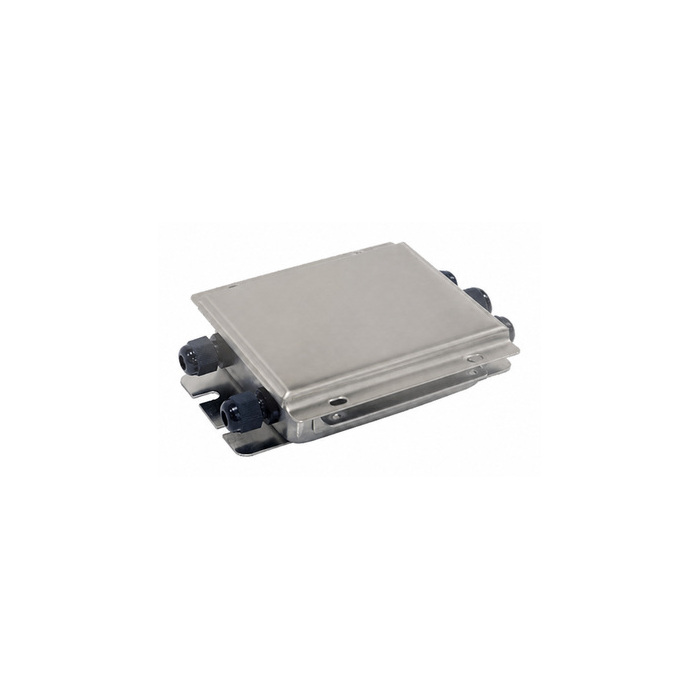
A junction box connects and often trims several load cells before their combined signal reaches an indicator or transmitter. It cannot correct a binding structure, but it can compensate modest sensitivity differences after mechanics are verified. Poor sealing, corroded terminals, wrong shield practice or excessive trimming can create drift and hide a failing channel. Selection should match cell resistance and wiring, environmental exposure, adjustment method, service access and the diagnostics required to maintain a multi-sensor scale.
Define the summing architecture
Record number of cells, four- or six-wire circuits, individual bridge resistance, excitation and rated output. Confirm whether the indicator supplies sense lines through the box. Calculate total parallel resistance and excitation current. Provide spare channels only when they do not complicate sealing or identification.
Choose an appropriate trim method
Resistive corner trimming can reduce stronger channel output but cannot increase a weak cell or repair mechanics. Compare adjustment range, resolution and stability with expected cell tolerances. Digital junction boxes may provide individual diagnostics but add configuration, power and communication requirements.
Match the environment
Specify indoor, outdoor, washdown, submerged, corrosive, dusty and hazardous conditions. Select enclosure, glands, terminals, venting and materials accordingly. Mount where water cannot collect and cables form suitable drip loops. An enclosure rating depends on correct gland size and installation.
Protect signal integrity
Keep cell and home-run cables shielded and separated from power conductors. Maintain documented shield continuity and grounding. Avoid long untwisted tails. Use surge protection suitable for the low-level bridge without adding unacceptable leakage or imbalance, especially on outdoor weighbridges and silos.
Make every channel identifiable
Label each cell by physical position and terminal. Record color-to-function mapping from the exact sensor, not assumptions. Provide safe access to individual excitation, signal, resistance and insulation checks. A sealed box should still support controlled troubleshooting without swapping undocumented wires.
Commission mechanics before trimming
Inspect support level, clearances, piping and individual zero outputs. Apply a known load at centre and defined corners or supports. Correct binding, height and load distribution first. Trim only the residual sensitivity difference, then recheck centre span and all positions.
Seal and document the result
Record individual pre-trim and post-trim outputs, adjustment positions, excitation and environmental condition. Tighten glands and lid according to instructions and inspect seals. Store photographs and a wiring diagram. Verify that closing the box does not pinch cables or change readings.
Maintain by evidence
Inspect moisture, corrosion, loose terminals, surge devices and trim stability. Compare individual signals when corner error or zero drift appears. Recalibrate after cell, cable, box, trim or structural changes. Avoid using trim repeatedly to mask a deteriorating load path.
Engineering checklist
- Calculate parallel bridge resistance.
- Select stable, limited trimming.
- Use correct glands and drainage.
- Label each physical cell channel.
- Correct mechanics before adjustment.
- Record individual signals and trim.
Frequently asked questions
Can a junction box fix an overloaded cell?
No. It can balance signal sensitivity but cannot change mechanical load or repair damage.
Why does moisture cause unstable weight?
Leakage across high-impedance signal paths changes bridge output and insulation.
Should every corner be trimmed to one reading?
Only within the approved procedure after confirming mechanics and rechecking full span.
Decision record
Record the selected architecture, operating cases, assumptions, accepted limits and responsible approver. Attach drawings, calculations, calibration evidence and unresolved deviations. Include inspection interval, spare strategy, fault response and recoverable configuration location. Assign an owner and closure date to each conditional acceptance. Review actual drift, faults and maintenance findings after representative service, and revise the engineering basis when evidence contradicts an assumption. Make the record available to operations and maintenance, with revision history and asset identity, so later adjustments can be compared with the accepted baseline rather than treated as undocumented tuning.
Need a project-specific review? Send load cases, drawings, environment, signal requirements and acceptance criteria through our contact page.
