


 Chinese
 Spanish
 Russian
 Portuguese
 French
 German
 Indonesian
 Thai
 Vietnamese
 Arabic
 Italian
 Turkish
 Polish
 Japanese


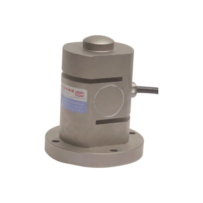

METRAVON MV-LC0043 is a flange-mounted compression load cell reference with a raised top contact and slots in the cylindrical body. Its 10-30 t family differs from the free-ended column arrangements of MV-LC0041 and MV-LC0042. The base is located through a flange, while the intended measured reaction enters through the upper contact. Keep the supporting face, contact member and clearance around the slotted body in the installation review.
Fix the flange-mounted compression load cell through its intended base
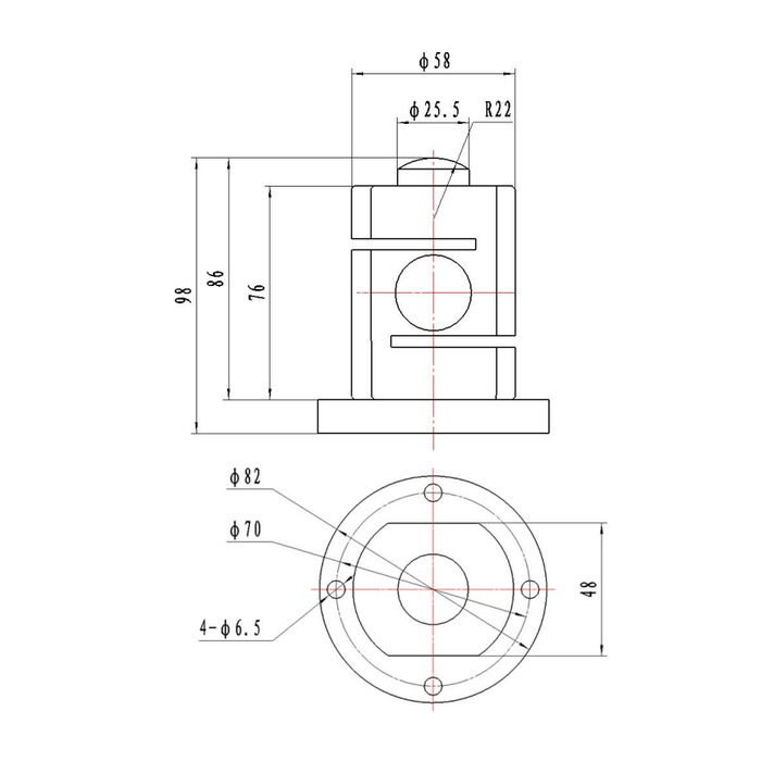
The reference base flange is 82 mm in diameter, with four diameter-6.5 holes on a 70 mm circle. The main body diameter is shown as 58 mm. Obtain the released support-face and fastener requirements for the selected unit before machining the base. The four holes locate an attachment pattern; their diameters do not establish a permitted bolt torque or prove that an unsupported flange can bridge an opening. The foundation and bearing contact must carry the reaction as required by the approved assembly.
| Item | Value | Selection notes |
|---|---|---|
| Technical compression family | 10-30 t | Confirm the actual rated body and intended load contact. |
| Base flange / main body diameter | 82 / 58 mm | Support the flange according to the released base detail. |
| Base holes / pitch circle | Four 6.5 mm holes / 70 mm | Do not infer bolt torque or unsupported flange strength. |
| Top contact reference | 25.5 mm / R22 | The surrounding upper body is not an additional load-bearing platen. |
| Overall / other vertical references | 98 / 86 / 76 mm | Keep the complete contact and base section with these values. |
| Protection entry | IP67 | No IP68 or immersion allowance is transferred from other models. |
Load the upper contact without clamping the slotted body
The top contact is marked with a 25.5 mm diameter and an R22 profile reference. Overall height is shown as 98 mm, with separate 86 and 76 mm vertical references in the outline. Match the contact member to the intended upper surface and keep nearby tooling from resting on the surrounding body. The two slots are not attachment points or channels to fill with packing material. A rigid collar, cover or debris that bridges a slot can restrain the sensing structure and change the measured response.
Specify exposure using IP67 rather than another column model rating
MV-LC0043 lists IP67, not the IP68 entry of some neighbouring heavy-load models. Describe pit water, cleaning, condensation and the location of the cable junction before accepting the installation. The -40 to +85 deg C operating entry also does not determine compatibility with a corrosive medium or an immersed termination. Ask for the actual material configuration and cable assembly. Do not extend a similar product family enclosure rating to this flange-mounted body.
Use the higher-resistance bridge in the acquisition review
Rated sensitivity is 2.0 +/-0.015 mV/V, supplied at 10-12 V DC excitation. Input resistance is listed as 780 +/-20 ohms and output resistance as 700 +/-5 ohms. Select the reader and any external weight transmitter around those entries and the useful load interval. Confirm terminal functions from the delivered unit record because the signal-colour list disagrees with the circuit sketch. For a replacement, check the other cells and channel setup instead of assuming that a common 2 mV/V nominal signal provides a matched weighing network.
Verify contact and restraint before accepting the loaded result
Provide the largest support reaction, normal working forces and reference points required for acceptance. Compare repeated compression and unloaded return with the actual base, top contact and cable secured. Check that normal movement does not bring a guide or guard into contact with the body. The 0.05% FS precision entry and 0.05% FS per 10 deg C temperature effect do not supply a whole-vessel accuracy. Safe load is 200% FS, without a separate approved impact duty, dynamic rail test speed or load rating for a proposed retaining guard.
Flange support, slotted clearance and wet locations
Q1. Can a collar around the cylinder be used to hold it in place?
The slotted body should not be treated as a generic clamping surface. Use the approved flange attachment and ask for any required retention detail. A collar that bridges the active structure can alter load transfer even if the empty indication can be zeroed.
Q2. Do the four mounting holes define the full load-bearing support?
They define the reference pattern, not the required bearing area or base stiffness. Obtain the support-face detail and make sure the reaction passes into a suitable foundation. Do not assume the flange may span a cut-out from hole positions alone.
Q3. Can it replace an IP68 column cell in a wet pit?
Not solely on capacity or sensitivity. This reference is IP67 and uses a different flange and contact arrangement. Compare the required exposure, support geometry and delivered sealing configuration before accepting a replacement.
