


 Chinese
 Spanish
 Russian
 Portuguese
 French
 German
 Indonesian
 Thai
 Vietnamese
 Arabic
 Italian
 Turkish
 Polish
 Japanese


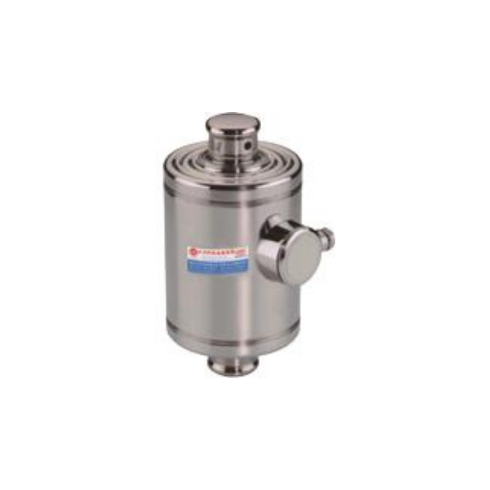

METRAVON MV-LC0042 is a column load cell reference for heavy weighing installations. Its drawing includes both a bare-cell view and an arrangement with upper and lower connecting plates. A buyer must identify which arrangement is required before using the quoted height or hole pattern. The technical range is 10-50 t, but the available drawing does not establish that every rated version includes the illustrated plates or has identical installation dimensions.
Separate the column load cell envelope from the complete assembly
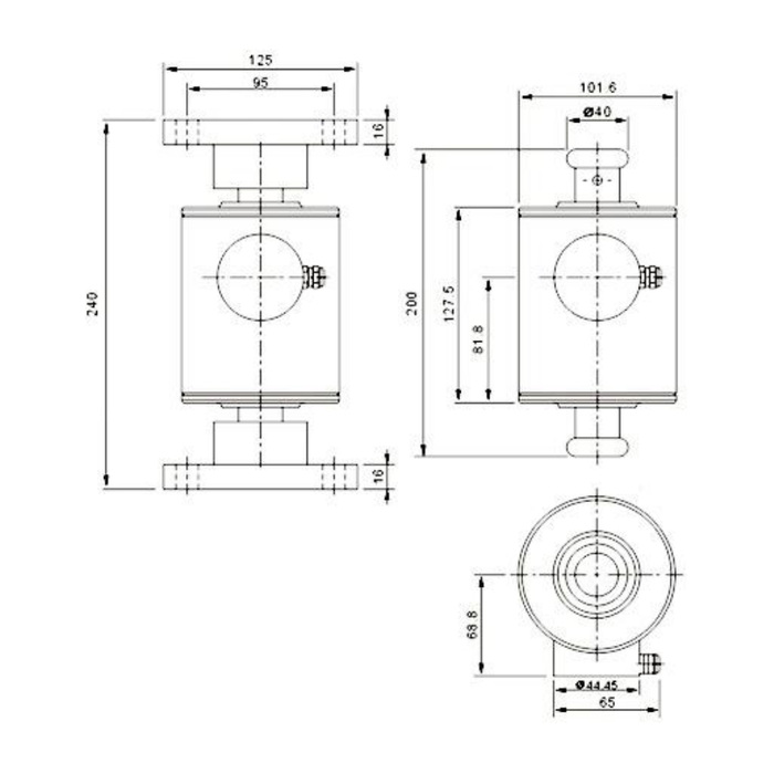
The bare-cell view carries a 200 mm end-to-end reference, while the arrangement with plates is marked 240 mm. The plate view gives a 125 mm span, a 95 mm hole-position reference and 16 mm plate thickness annotations. Confirm the actual top and bottom connections, including holes, fasteners and load-bearing faces. The difference between the two height references should not be reconstructed by adding plate thicknesses alone: the illustrated contact parts and engagement also belong to the assembly.
Ask the offer to identify every connecting component
List whether the purchase covers the sensing cell, the two plates, contact adapters, retaining parts and any site-specific fasteners. The original photo shows the sensor without the plate arrangement. It cannot prove a complete weighing module is included. If existing plates are retained, submit their dimensions, condition and mating contacts. Do not force two retained plates into alignment by tightening them against the sensor, or assume a flange sketch establishes tensile measurement approval for the assembled unit.
Check side access and the structure around the plates
The side view includes a 101.6 mm envelope reference and a 40 mm upper-end diameter annotation. The lateral housing, cable fitting and tool clearance need their own space. Show where load enters the upper assembly, where the lower assembly bears on the foundation and how lateral movement is controlled. The drawing does not provide a permissible side load, plate bending allowance or fastening torque. Those requirements must be resolved with the rated installation rather than assigned from a nominal 10-50 t range.
| Item | Value | Selection notes |
|---|---|---|
| Technical rated family | 10-50 t | Match the selected unit to a complete installation drawing. |
| Bare-cell / plated-assembly height references | 200 / 240 mm | Confirm the actual supplied combination before setting support height. |
| Plate span / hole-position reference | 125 / 95 mm | Obtain full hole, fastener and bearing-face details. |
| Plate-thickness annotations | 16 mm | These references do not by themselves define the full assembled height. |
| Side-envelope reference | 101.6 mm | Add cable, access and surrounding movement clearance. |
| Bridge sensitivity | 2.0 +/-0.015 mV/V | Check excitation load using the 780-ohm input specification. |
Verify the cell and the finished support in different stages
Confirm the delivered identification, terminal functions and bridge response first, then check the assembled support with agreed reference forces or weights. The electrical entries are 2.0 +/-0.015 mV/V at 10-12 V DC excitation, 780 +/-20 ohms input and 700 +/-5 ohms output resistance. The reference signal-colour legend conflicts with its circuit, so do not select polarity from colour alone. Inspect plate seating and unloaded return before applying indicator corrections. A completed electrical check cannot exclude a binding or distorted connecting plate.
Set acceptance for the real vessel or scale installation
Supply permanent dead load, greatest support reaction and the useful weight interval, together with the final connection drawings. The precision entry is 0.05% FS; it does not include every plate, restraint or foundation contribution. Temperature effect is listed as 0.05% FS per 10 deg C and operation as -40 to +85 deg C. Review IP68 exposure conditions and the cable termination on the actual offer. The 200% FS safe-load limit is not a test instruction for the flanged assembly, nor does the reference application list certify a dynamic rail or vehicle-scale result.
Bare cells, connecting plates and the supply list
Q1. Are the top and bottom plates included with the cell?
The drawing illustrates an arrangement, not a supply list. Require the quotation to identify the plates and all connecting hardware explicitly. The bare-cell photo and the assembly view should not be treated as the same delivered configuration.
Q2. Can the 240 mm assembly height be replaced by a 200 mm sensor directly?
Only after redesigning or confirming the complete load-transfer arrangement. The two dimensions refer to different views with different connecting components. Reusing the shorter dimension without checking the contacts can leave the supported structure at the wrong datum or impose preload.
Q3. Does a plated arrangement establish tension capability?
Not from these references. If a project imposes lift, tension or load reversal, obtain an explicit approved arrangement and calibration scope. A plate at each end is not sufficient evidence of a tensile measurement rating.
Q4. What information is needed for a replacement quotation?
Send the actual top and bottom plate views, retained contacts, required support height and maximum reaction. Identify which components must be supplied and the reader being retained. That allows the offer to distinguish a replacement cell from a complete mechanical assembly.
