


 Chinese
 Spanish
 Russian
 Portuguese
 French
 German
 Indonesian
 Thai
 Vietnamese
 Arabic
 Italian
 Turkish
 Polish
 Japanese


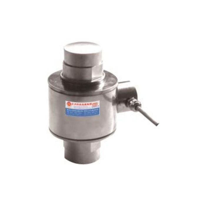

METRAVON MV-LC0040 is a column load cell with a base-plate assembly shown in its reference drawing. For a heavy vessel or weighing platform, this arrangement should be evaluated from the foundation upward: plate footprint, bolt centres, lower contact, sensor and upper loading part. The technical range is 10-60 t. That range does not establish that one illustrated set of mounting dimensions applies to every offered rated assembly.
Set out the base from hole coordinates, not the outside rectangle
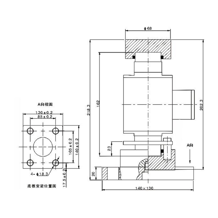
The base plan is 140 by 130 mm, with four diameter-18.3 holes. Their centre spacings are 105 +/-0.2 and 85 +/-0.2 mm; the outer dimensions carry their own +/-0.2 mm annotations. A 17.5 +/-0.2 mm edge-offset reference is also shown. Keep the two axes clear on the foundation plan. Neither the outer rectangle nor the sensor body centre alone defines the drilling pattern. Confirm the selected rated base drawing before issuing an anchor or adaptor-plate layout.
| Item | Value | Selection notes |
|---|---|---|
| Base outer dimensions | 140 x 130 mm | Use the rated plan with the stated dimensional tolerances. |
| Hole-centre spacings | 105 +/-0.2 x 85 +/-0.2 mm | Keep orientation consistent with the foundation drawing. |
| Four base holes | 18.3 mm diameter | Fastener selection and structural checks remain separate. |
| Illustrated total height | 218.3 mm | The 202.3 and 162 mm references use different datums. |
| Base thickness / upper contact | 20 mm / 68 mm diameter | Confirm these belong to the offered complete assembly. |
| Bridge input / output resistance | 380 +/-20 / 350 +/-5 ohms | Identify the reader and number of connected supports. |
Allow for the complete column load cell and base assembly height
The section gives 218.3 mm across the illustrated assembly and a separate 202.3 mm vertical reference. Other annotations include 162 mm, a 20 mm plate thickness and a diameter-68 upper contact part. These references start and end at different surfaces; they should not be substituted for one another when setting a vessel elevation. Ask the assembly supplier to mark the exact bearing datums and the installed height for the selected rating. Confirm whether the upper part, lower seat, plate and retention hardware are in the quotation.
Keep retention hardware from creating an unintended force path
The drawing includes lower hardware around the seating arrangement, but it does not assign the whole assembly a lateral, uplift or seismic rating. Ask how the sensor is retained and where the normal compression is transferred. Design guides, lift-off protection and vessel restraints for the actual structure, while preserving the intended weighing contact. Do not turn a visible fastener into an assumed load-bearing tie or tighten it by a torque inferred solely from the base-hole diameter.
Select the electrical channel for the intended multi-support layout
MV-LC0040 is documented as a 2.0 +/-0.015 mV/V bridge with 10-12 V DC excitation. Input resistance is 380 +/-20 ohms and output resistance is 350 +/-5 ohms. Provide the number of supports, reader and any junction-box arrangement so their excitation and measurement requirements can be checked. The channel is not inherently 4-20 mA or Modbus RTU; those functions need an appropriate specified conditioner. Confirm the delivered wiring and loading sign because the reference signal-colour legend disagrees with its circuit.
Accept the installed vessel rather than just the empty display
Measure the relevant support reactions or justify them from the structural design, including tare and maximum contents. After safe installation, inspect seat clearances and restraint contacts before recording zero, reference loads and repeat unloading return. Where pipework or guides can affect the vessel, compare readings under the agreed connected operating condition. Reference precision is 0.05% FS, not an installed-system guarantee. IP68, material choice and the -40 to +85 deg C operating interval need to be checked against actual exposure; the stated 0.05% FS per 10 deg C temperature effect still matters. Do not use the 200% FS safe-load limit as a proof-test target for the foundation or assembly.
Base fabrication, vessel elevation and restraint
Q1. Should the foundation holes follow the 140 by 130 mm rectangle?
Those are outside base dimensions. The reference hole centres are 105 by 85 mm, each with a +/-0.2 mm annotation. Obtain the final plan for the offered rating and mark the axes before setting out holes or making an adaptor.
Q2. Does the lower hardware make this an anti-uplift weigh module?
No uplift rating is established by the drawing alone. Ask for the approved retention function and load rating of the complete assembly. If the vessel needs lift-off or seismic restraint, that requirement needs its own mechanical confirmation.
Q3. Which height belongs on the vessel support drawing?
Use the confirmed installed bearing-to-bearing dimension for the supplied assembly. The reference shows 218.3 mm overall, but also has 202.3 and 162 mm annotations on different datums. Have those surfaces identified rather than choosing whichever number fits the available gap.
Q4. What information makes a multi-support enquiry usable?
Include the foundation and vessel-leg plans, tare and maximum contents, expected unequal reactions, pipe connections and required weighing increments. Identify the reader, support count and exposure. Ask the offer to separate the column cell from the base, contacts, retention parts and any signal conditioner.
