


 Chinese
 Spanish
 Russian
 Portuguese
 French
 German
 Indonesian
 Thai
 Vietnamese
 Arabic
 Italian
 Turkish
 Polish
 Japanese


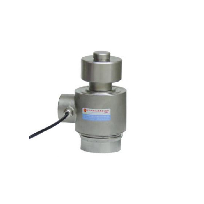

METRAVON MV-LC0039 is a 10-30 t column load cell whose reference section includes upper and lower seat parts. Those parts matter when a heavy weighing support is quoted or replaced: the complete contact assembly occupies more height than the inner sensor span shown on the same drawing. Define the retained seats and supplied parts before comparing this product with a bare column or selecting a support height.
Read the column load cell section from bearing face to bearing face
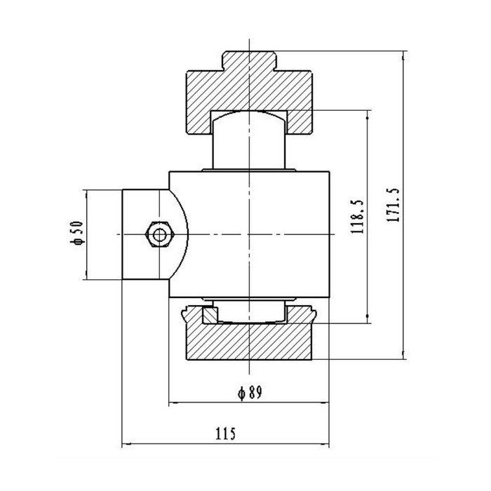
The reference shows 171.5 mm across the illustrated assembly and a separate 118.5 mm internal vertical span. The latter should not be used as the complete installed height. A diameter-89 body and 115 mm overall lateral span appear in the same view, together with a diameter-50 side-feature reference. Show the surrounding pocket and cable route on the installation section. Obtain the rated drawing with defined datums rather than subtracting these dimensions to design individual seat parts.
Decide whether the quote is for a bare sensor or a seated unit
The upper component surrounds the curved upper contact; the lower view shows a separate supporting part and contact interface. Ask which parts are included, how they are retained and which existing components may remain. A photograph is not a complete assembly bill of materials. Verify contact form and allowed movement with the offered drawing. No spherical contact in the illustration establishes unlimited self-alignment, an uplift restraint or permission to carry sustained lateral forces through the column.
Verify the 350-ohm output channel during a replacement
The electrical reference is 2.0 +/-0.015 mV/V with 380 +/-20 ohms input resistance and 350 +/-5 ohms output resistance, excited at 10-12 V DC. This differs from the approximately 700-ohm output bridges documented for some other column models. Do not approve a mixed set from the common sensitivity alone. Have the indicator or junction-box arrangement checked for the proposed combination, then confirm excitation, delivered terminal functions, signal direction and calibration. If a PLC needs 4-20 mA or RS485, specify a suitable external weighing conditioner rather than describing the raw bridge as that interface.
| Item | Value | Selection notes |
|---|---|---|
| Nominal technical range | 10-30 t | Ask for the offered rating and its matching contact parts. |
| Illustrated assembly height | 171.5 mm | Includes the contact arrangement shown in the section. |
| Separate vertical span | 118.5 mm | Not a substitute for total installed height. |
| Body diameter / lateral span | 89 / 115 mm | Allow for the side feature and cable access. |
| Input / output resistance | 380 +/-20 / 350 +/-5 ohms | Reader compatibility is not proved by 2 mV/V alone. |
| Reference enclosure rating | IP68 | Agree actual sealing and exposure conditions for the supplied unit. |
Investigate support restraint before adjusting the scale
For a vehicle platform or heavy vessel, inspect the upper and lower contacts under safely unloaded conditions and check for objects that can bridge the weighing gap. Guides, accumulated debris and displaced seating parts can alter the reaction transmitted through the sensor. Use a mechanically safe test sequence agreed for the structure, then compare the relevant load positions and return to empty. The 0.05% FS sensor precision entry does not remove the need for those installed checks or establish an approved dynamic rail-weighing result.
Define exposure and supply scope in the order
IP68 is listed, but the reference does not establish a universal depth, duration or cleaning-pressure allowance. Include actual exposure, cable termination position and alloy-steel or stainless-steel requirements in the enquiry. The operating interval is -40 to +85 deg C, with temperature effect listed as 0.05% FS per 10 deg C. A 200% FS safe-load entry is not a structural rating for the seat set. Separate the sensor rating, mating-part approval and site acceptance requirements instead of assigning one number to the complete support.
Where a base plate is required, the MV-LC0040 base-assembly reference provides a different foundation layout to review. Confirm the complete rated arrangement instead of treating the two seat designs as interchangeable.
Seated height and mixed-cell replacements
Q1. Can I design a 118.5 mm-high gap around this unit?
That reference is an internal span, while the shown seated assembly is 171.5 mm high. Request the rated section and identify which bearing faces define the available gap. A bare sensor and a complete contact assembly need different comparisons.
Q2. Can existing upper and lower seats be reused?
Only after checking their geometry, condition and permitted contact with the offered sensor. Identify every retained part on the enquiry drawing. A similar appearance or nominal capacity does not confirm the seating fit or installed reaction.
Q3. Is this a drop-in replacement for a 700-ohm column cell?
Not on the evidence of equal mV/V output. The documented output resistance here is 350 +/-5 ohms. Check the full electrical and mechanical arrangement with the reader and scale supplier, then perform the agreed calibration and load-position checks.
