


 Chinese
 Spanish
 Russian
 Portuguese
 French
 German
 Indonesian
 Thai
 Vietnamese
 Arabic
 Italian
 Turkish
 Polish
 Japanese


Radar Level Antenna Protection: Rain, Condensation, Sun and Alignment
Rain, condensation, solar heating and mounting movement can degrade an otherwise suitable radar installation. The protection package should keep the housing and radiating face within their documented limits while preserving the measurement path.
Droplets on the antenna are a wavelength problem
The free-space wavelength is approximately 3.75 mm at 80 GHz and 11.5 mm at 26 GHz. Droplets, water films and deposits can alter antenna transmission or create unwanted returns. Their effect also depends on antenna design, coating, path length and installation; wavelength alone does not establish which instrument will fail in rain.
Responses, in order of preference:
Use an approved antenna orientation and drip-management arrangement. Do not assume that a vertical nozzle keeps a downward-facing antenna dry; condensation can collect on that face or drip from the nozzle wall.
Keep any housing weather shield or rain hood outside the radiating path and follow its installation drawing. A metal cap in front of the antenna can block the measurement even when it is beyond the near-zone limit.
Use a purge only where the instrument and process design permit it. Specify the gas, dryness, cleanliness, flow, pressure and discharge arrangement for the actual fitting. An arbitrary flow may cool the face, increase gas consumption or change vessel conditions rather than solve condensation.
Acceptance criteria in rain: agree with the supplier what reading stability is expected in specified rainfall, or the discussion happens for the first time during a storm.
Separate external antenna condensation from moisture inside the electronic housing. For housing moisture, check seals, glands, plugs and approved breathing or drying provisions. Do not add a breather that compromises enclosure or explosion-protection certification.
Solar loading is an electronics problem wearing a weather mask
A dark housing in full sun can run 20–30 °C above ambient, and inside it the transmitter is at its electronics limit on hot days. Standard responses:
a sun shade / radiation shield above the housing, ventilated, not touching it;
light-colored or reflective housing finish where the site allows;
check combined process and ambient limits, solar exposure and measured housing temperature. A 40 °C ambient site does not automatically provide adequate margin for electronics near a hot process.
The sun also ages cable jackets and gasket elastomers; UV-rated cable and an inspection interval for external gaskets belong in the same review.
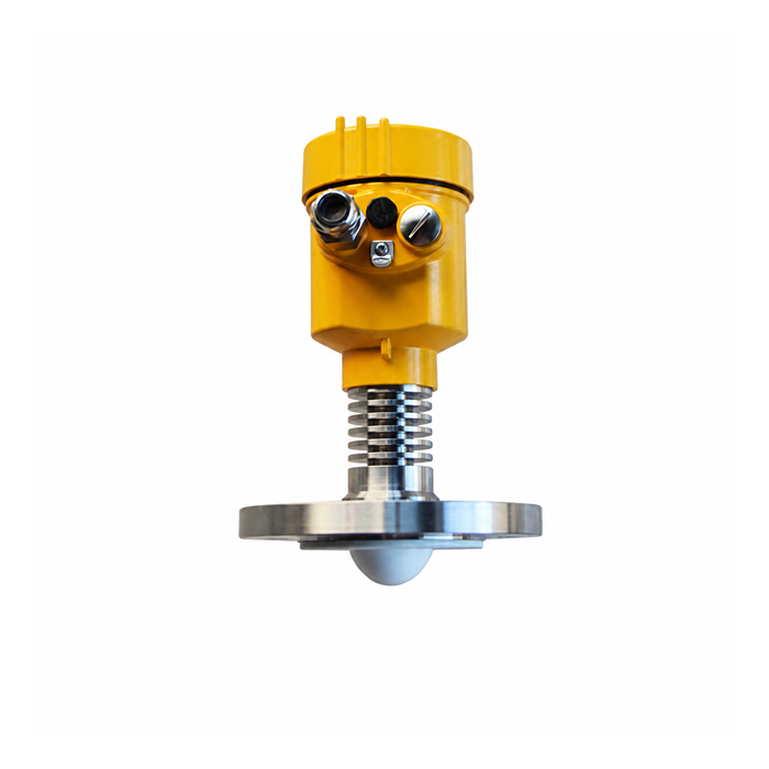
Alignment: tilt multiplies with distance
The beam leaves the antenna along its axis. Tilt the antenna by θ and the beam centre misses the intended target point by:
offset = H × tan θ
Worked example. Tank height 15 m, antenna tilt 1° → 15 × tan 1° ≈ 15 × 0.0175 = 0.26 m of offset at the bottom. On a 4 m tank the same tilt gives 7 cm. The tolerance that matters is not degrees at the flange; it is where the beam lands at the measurement surface — relative to tank internals, fill stream, and the lowest level of interest.
Alignment checks worth doing on installation:
confirm verticality with a level on the antenna axis, not on the nozzle (nozzles lean);
for angled installations on conical roofs, use the manufacturer's aiming tolerance and check the beam footprint against internals at the farthest measuring distance;
after any nozzle or roof work, re-verify — alignment is a one-time accident waiting to be repeated.
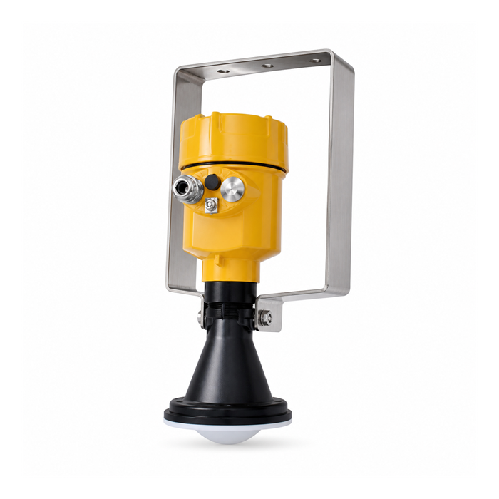
A protection checklist that survives commissioning
Weather shield fitted with clearance; not touching the antenna or housing
Drainage path away from the face; no drip edge above an upward-facing antenna
Purge connection available where condensation is credible, with supply agreed
Housing sun shade fitted; internal temperature verified on a hot day, once
Antenna verticality recorded with the commissioning record
Cable UV-rated; glands sealed; spare gland plugged
Record diagnostic curves under representative dry and wet conditions using an approved test procedure. Do not hose a live installation or teach a wet-face or real product echo as a permanent obstruction without the manufacturer’s procedure.
Questions from outdoor installations
Q1. Does a rain shield hurt the measurement?
It can if it enters the radiating path or creates an unwanted return. Use the approved clearance and mounting drawing, then verify the echo curve; being outside the near zone does not make a shield invisible.
Q2. Is nitrogen purge worth the cost?
Compare an approved purge with drainage, antenna design, cleaning and mounting improvements. Include gas compatibility, supply reliability and operating cost; nitrogen is not a universal cure for condensation or icing.
Q3. Can misalignment be corrected in software?
Mapping hides fixed echoes; it does not move the beam. Fix the mechanical alignment, then map.
