


 Chinese
 Spanish
 Russian
 Portuguese
 French
 German
 Indonesian
 Thai
 Vietnamese
 Arabic
 Italian
 Turkish
 Polish
 Japanese



The METRAVON MV-RD14 is an 80 GHz liquid-level radar with a 44 mm PTFE lens. Threaded and flanged assemblies provide different mounting choices for storage and process vessels. Select the connection around the existing nozzle and process conditions, rather than choosing a flange size from the antenna diameter alone.
Will the 44 mm lens fit the vessel nozzle?
Start with the nozzle's clear internal diameter, length and internal projections. A nominal pipe size does not describe the available opening after a lining, gasket or valve is fitted. The lens needs a clear view of the liquid; a recessed antenna or an obstruction at the opening can produce a strong fixed echo close to the instrument.
The MV-RD14 has a nominal 6-degree beam. Its footprint increases with distance, so an installation that clears a nearby agitator at high level may still encounter vessel fittings lower down. Provide a sectional drawing showing the nozzle, agitator sweep, coils and inlet position. Do not assume that a narrower beam removes the need for this drawing.
MV-RD14 operating options
| Item | Options | What to specify |
|---|---|---|
| Frequency and antenna | 80 GHz; 44 mm PTFE lens | Liquid composition, vapour, coating and cleaning conditions. |
| Distance range | Up to 30 m | Nearest and farthest surface positions measured from the antenna reference plane. |
| Threaded connection | G1 1/2 A option | Actual mating thread and sealing arrangement, not just the nominal pipe diameter. |
| Flanged connection | Selected flange assembly | Standard, nominal size, pressure designation, facing and material. |
| Temperature options | Standard / high-temperature assembly | Normal, upset and cleaning temperatures; the high-temperature version is a separate configuration. |
| Electrical output | 4-20 mA/HART or RS485/Modbus option | Supply voltage, wiring arrangement and the receiving PLC or instrument. |
The configured assembly sets the allowable pressure and temperature together. A PTFE lens does not make every seal, flange or housing suitable for the same service. Obtain the pressure-temperature limits for the chosen connection and seal before approving the order; maximum values from different options should not be combined.
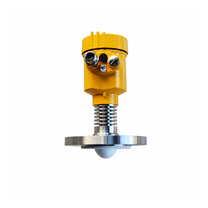
Heating, cleaning and the electronics enclosure
For heated vessels, the process connection and the electronics do not necessarily operate at the same temperature. Keep the heat-dissipating section exposed as required by the installation drawing; extending tank insulation around it can undermine the intended cooling. Include steam cleaning or hot flushing in the temperature assessment even when normal operation is cool.
Where high-temperature service is central to the application, compare the dedicated MV-RD14G before specifying the assembly. Neither a product photograph nor a similar model name establishes the delivered rating.
Check the echo before accepting the installation
Record the empty-vessel geometry and inspect the echo response to fixed internals. Configure any false-echo suppression using the manufacturer's procedure and a known liquid position, so the real surface is not accidentally excluded. Observe filling and draining, particularly near the nozzle and around agitator operating states.
Acceptance should compare a reference level, the local reading and the controller reading at agreed operating points. Also test the selected fault indication. A correct local display with an incorrectly scaled 4-20 mA input can still give the control system the wrong level.
Connection and application questions
Q1. Can a reducing adaptor make an existing nozzle suitable?
It may solve the mechanical connection while making the radar path worse. Check the adaptor bore and total recess depth with the antenna drawing. A stepped or long passage needs an installation assessment rather than approval based only on thread compatibility.
Q2. Is the radar suitable for a foaming liquid?
That depends on the foam and process conditions. Dense or persistent foam can weaken or alter the surface echo. Describe foam thickness, agitation and changes during filling, and include those operating states in the trial or acceptance plan.
Q3. Does the product page establish hazardous-area approval?
No. For a hazardous location, the quotation must identify the exact certified variant and applicable certificate, marking and installation conditions. Those documents must match the supplied instrument and the site's classification.
Q4. What is needed for a replacement quotation?
Provide the existing nozzle drawing, instrument nameplate, liquid and temperature-pressure envelope, wiring diagram and measurement span. Include the reason for replacement, especially if the old device loses echoes near a particular level; a new radar mounted in the same unsuitable geometry may reproduce the fault.
