


 Chinese
 Spanish
 Russian
 Portuguese
 French
 German
 Indonesian
 Thai
 Vietnamese
 Arabic
 Italian
 Turkish
 Polish
 Japanese



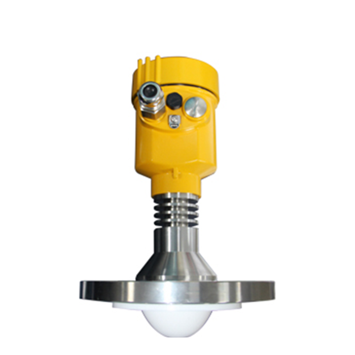
METRAVON MV-RD15 is a long-range radar level meter for liquids. Its 76 mm PTFE lens produces a 3-degree beam, with listed distance configurations of 0.1-30 m and 0.3-150 m. Choose between them using the empty-tank distance and nearest permitted liquid surface, not simply the vessel's nominal height.
Choosing the distance range for a long-range radar level meter
The empty distance runs from the instrument's measurement reference plane to the lowest surface that must be measured. A mounting nozzle above the roof adds distance. At the other end of the span, a high liquid level can enter the near zone even if the tank is well below the maximum range. Record both distances on the enquiry drawing.
| Distance range | Before ordering |
|---|---|
| 0.1-30 m | Check the lowest operating surface and nozzle offset against the full distance. |
| 0.3-150 m | Confirm the selected range and usable echo at the actual liquid surface. |
The 150 m rating does not mean every liquid can be measured at that distance under any process condition. Foam, weak surface reflection, condensation and interference can limit usable performance. A long-range option also does not remove the need for clearance at the highest level.
Check the beam path at the bottom of the tank
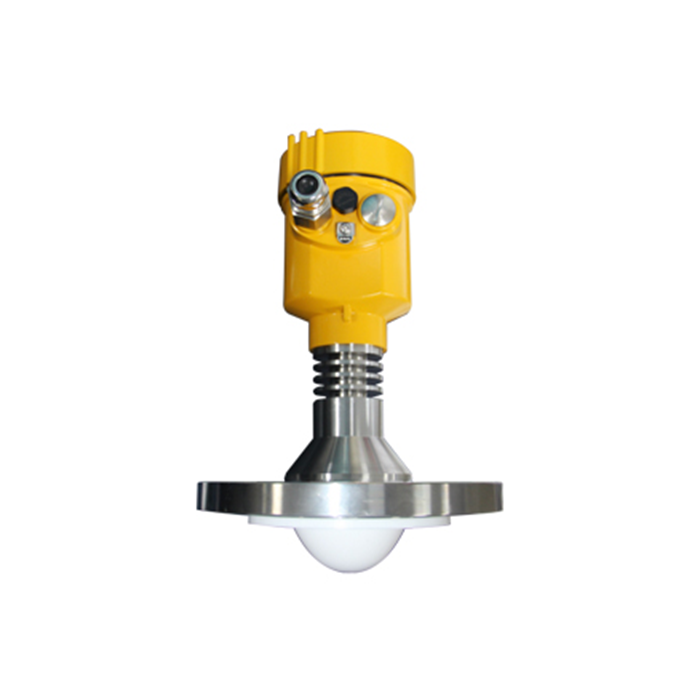
A narrow beam is useful where ladders, coils or supports occupy part of the vessel. It still widens with distance. Review the path at the lowest operating level, where it is widest, and keep the antenna away from the inlet stream. Nozzle echoes and internal metalwork should be investigated before increasing filtering to conceal an unstable reading.
MV-RD15 is specified here for liquid measurement. For hot bulk solids, compare the separate MV-RD21G solids model; similarity in frequency and lens diameter does not establish identical media suitability or pressure limits.
Process and electrical specifications
| Parameter | Value or configuration |
|---|---|
| Operating principle | 80 GHz FMCW |
| Antenna | 76 mm PTFE lens, 3 degrees |
| Process connection | Flange, DN80 or larger |
| Process temperature | -40 to 180 deg C |
| Process pressure | -0.1 to 2.5 MPa |
| Stated measuring accuracy | +/-2 mm |
| Two-wire option | 24 VDC, 4-20 mA/HART |
| Other electronics | Separate AC-powered and RS485/Modbus configurations; specify the terminal arrangement. |
| Housing protection | IP67 metal housings; IP65 ABS option. Select suitable glands and seals. |
Verify flange, seal and exposed materials against the combined temperature, pressure and liquid chemistry. The listed accuracy is an instrument specification, not an installed-volume tolerance. Vessel geometry, reference-height entry and the receiving system also affect the final reported quantity.
From a distance reading to a PLC level value
For a 4-20 mA loop, enter the same level endpoints in the radar and PLC. Test both endpoints and an intermediate point; a correct displayed distance does not prove that PLC scaling is correct. For RS485/Modbus, obtain the register map for the supplied electronics and verify address, units, scaling, word order and fault status. Do not apply a water-level instrument's register map solely because it uses RS485.
Range and replacement questions
Q1. Should a 30 m tank automatically use the 30 m option?
Not necessarily. Include the distance above the tank roof and the lowest required surface. If the resulting distance is close to the range limit, have the geometry and echo conditions reviewed before selecting the option.
Q2. Can the 180 deg C version be used at 200 deg C?
The MV-RD15 process limit is 180 deg C. Review MV-RD15G for a 200 deg C requirement, including its flange, seals and electronics environment. A short temperature excursion is still an operating condition to declare.
Q3. What determines the quoted configuration?
The distance range, flange and materials, housing, supply and signal interface all affect the selected assembly. Send the tank section and process limits with the required PLC connection when requesting an MV-RD15 quote.
