


 Chinese
 Spanish
 Russian
 Portuguese
 French
 German
 Indonesian
 Thai
 Vietnamese
 Arabic
 Italian
 Turkish
 Polish
 Japanese



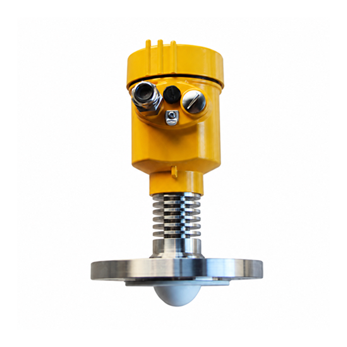
METRAVON MV-RD14G is an 80 GHz radar level meter for hot liquids, with a 44 mm PTFE lens and a flange connection starting at DN50. It measures surface distance without an immersed probe. Its smaller antenna can suit a restricted vessel opening, but the 6-degree beam still needs a clear path through the nozzle and into the tank.
Fitting an 80 GHz radar level meter to a smaller nozzle
Measure the nozzle bore, length and internal projections before choosing the flange. DN50 identifies a nominal connection size; it does not establish that every DN50 nozzle provides suitable clearance. A long neck, internal weld or nearby pipe can return an echo even when the flange bolts fit. Send a section drawing showing the antenna position relative to the nozzle outlet.
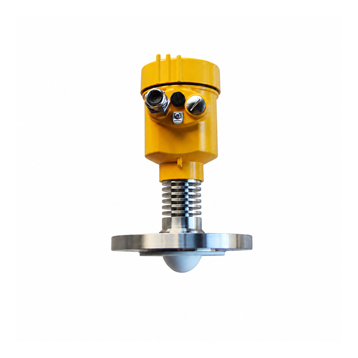
Dimensions and process limits that affect selection
| Item | MV-RD14G | Selection implication |
|---|---|---|
| Measuring medium | Liquid | Check foam, agitation, condensation and deposits for the actual liquid. |
| Distance range | 0.1-30 m | Measure from the radar reference plane, including the nozzle height. |
| Lens / beam angle | 44 mm PTFE / 6 degrees | Allow clearance along the full measurement path, especially near the tank bottom. |
| Connection | Flange, DN50 or larger | Specify flange standard, pressure class, facing and nozzle bore. |
| Process temperature | -40 to 200 deg C | Assess the seal and flange at the operating temperature and pressure together. |
| Process pressure | -0.1 to 2.5 MPa | The maximum temperature and pressure are not an automatic combined rating. |
| Stated measuring accuracy | +/-2 mm | This is not a guarantee of installed tank volume or control-system accuracy. |
The PTFE designation describes the lens. It does not establish compatibility of every exposed component or seal with a corrosive medium. Give the liquid composition, concentration and cleaning conditions when requesting materials. The process temperature limit also does not permit the electronics enclosure to operate at 200 deg C.
When a larger antenna deserves consideration
A vessel with a clear short measurement path may accommodate this 6-degree beam. For a taller tank with internal obstructions, compare the 76 mm, 3-degree MV-RD15G liquid radar, which requires a larger connection. Beam angle describes the main beam, not a hard boundary beyond which metalwork becomes invisible. Neither model should point directly at a filling stream.
Wiring and commissioning
A two-wire 24 VDC, 4-20 mA/HART configuration carries power and the analog signal on the same pair. An RS485/Modbus configuration uses a different wiring arrangement; it is not an extra connection available on every two-wire unit. Match the ordered electronics to the PLC input, power supply and terminal diagram before installation.
Set the reference height and the intended empty and full levels, then compare the measured distance with a safe independent reference. Check a low level, a normal operating level and the highest permitted level. Repeat the check during filling or agitation to expose echoes that a static test misses. Save the settings and echo record for subsequent fault diagnosis.
Installation questions
Q1. Can the liquid rise to within 100 mm of the antenna?
The listed range begins at 0.1 m, measured from the specified reference plane. Allow for level overshoot, foam and nozzle effects when setting the maximum operating level. Do not use the nominal lower limit as the only protection against overfilling.
Q2. Is every enclosure IP67?
No. The metal housing options are listed as IP67, while the ABS option is listed as IP65. Specify the housing, cable glands and sealing arrangement for the location; an enclosure rating does not establish chemical resistance or explosion protection.
Q3. What should accompany a retrofit enquiry?
Include the nozzle section, flange details, empty and full distances, liquid and process conditions, and the existing instrument wiring. For a hazardous area, request the certificate applicable to the exact ordered assembly rather than relying on an optional approval description.
Request an MV-RD14G quotation with the nozzle drawing and operating limits so the antenna fit, materials and electrical configuration can be specified together.
