


 Chinese
 Spanish
 Russian
 Portuguese
 French
 German
 Indonesian
 Thai
 Vietnamese
 Arabic
 Italian
 Turkish
 Polish
 Japanese



The METRAVON MV-RD13S bracket-mounted 80 GHz radar level meter uses a 76 mm PTFE lens to measure distance without touching the surface. A gantry mounting arrangement makes it suitable for evaluating open-water installations where a vessel nozzle is unavailable. The mounting position still determines whether the radar can follow the water through its full operating range: a long-range instrument cannot compensate for a moving bracket or an obstructed view.
Position the bracket before choosing the range
Measure from the antenna reference plane to both the highest and lowest expected water levels. Include flood conditions, not just the water level on the survey day. The high-water position must remain outside the selected instrument's near zone; low water sets the greatest measuring distance. The MV-RD13S has 30 m and 150 m range configurations, but minimum distance and accuracy must be matched to the offered version.
A rigid support should hold the antenna orientation after wind, vibration and maintenance access. Aim the radar at an unobstructed surface, away from a pier, wall, ladder or inlet jet. The nominal 3-degree beam narrows the illuminated area but does not make nearby metalwork irrelevant. Check clearance along the whole path, including the wider footprint at low water.
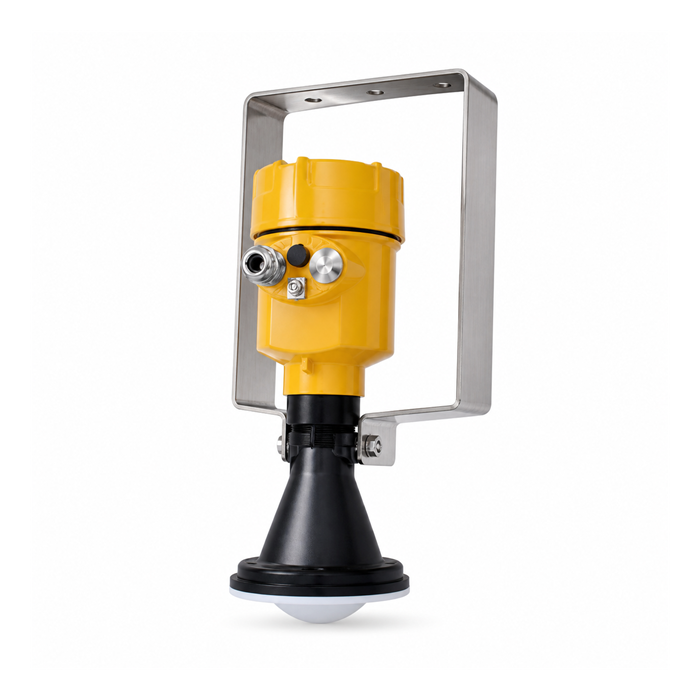
MV-RD13S configuration choices
| Item | Product reference | Site check |
|---|---|---|
| Measurement | 80 GHz radar | Measures antenna-to-surface distance; a surveyed reference is needed to report water elevation. |
| Antenna | 76 mm PTFE; 3-degree beam | Check the surface target and surrounding obstructions at both range extremes. |
| Range | 30 m / 150 m configurations | Specify the actual distance interval. Do not use the longest range as a guarantee for every surface condition. |
| Mounting | Gantry or flange option | The bracket drawing and support stiffness matter as much as the instrument dimensions. |
| Gantry temperature | -40 to 80 deg C | Assess local heat exposure and the cable rating; flange assemblies have separate limits. |
| Enclosure | Metal IP67 / ABS IP65 | Select the housing and cable-entry arrangement for rain, dust and maintenance exposure. |
This page addresses atmospheric installations. A flange option does not establish approval for a pressurized vessel. For a nozzle-mounted liquid application, also review the MV-RD13 configuration against the actual process connection.
Bring the measurement into the control system
Choose the electronics before assigning PLC or RTU channels. A 24 V DC two-wire 4-20 mA/HART arrangement and a separately powered RS485/Modbus arrangement require different wiring and inputs. An RS485 port alone does not confirm that the receiving device can read the instrument's registers.
During commissioning, compare the displayed distance with an independent reference. Then check the level calculation and the value received by the controller. Define how an invalid echo, power interruption or communication timeout is reported; holding an old value without a visible fault indication can conceal a rising water level.
Questions about bracket-mounted installations
Q1. Can the sensor be mounted on an existing handrail?
Only after checking rigidity, orientation and access. A handrail that moves when personnel use it may change the measuring geometry. A dedicated structural support is preferable where handrail movement cannot be controlled, and its final position should be included in the site survey.
Q2. Does the 150 m option improve a short installation?
Not automatically. A short installation may be limited by the high-water clearance, nearby structures or turbulence rather than maximum range. Select the version that covers the required distances and provides an acceptable echo under the site's conditions.
Q3. Can this model be used above powder or bulk material?
The product range includes solid-material applications, but an open-water selection cannot be carried over unchanged. Provide the material, dust conditions, filling direction and surface profile so the antenna orientation and usable range can be assessed separately.
Information to send with an enquiry
Send a side-view sketch showing the support, antenna reference plane, highest and lowest surfaces, and nearby structures. Add the medium, operating temperature, available power, required output, cable route and controller model. State whether you need distance, level above a local datum or elevation so the quotation and commissioning scope describe the same measurement.
