


 Chinese
 Spanish
 Russian
 Portuguese
 French
 German
 Indonesian
 Thai
 Vietnamese
 Arabic
 Italian
 Turkish
 Polish
 Japanese



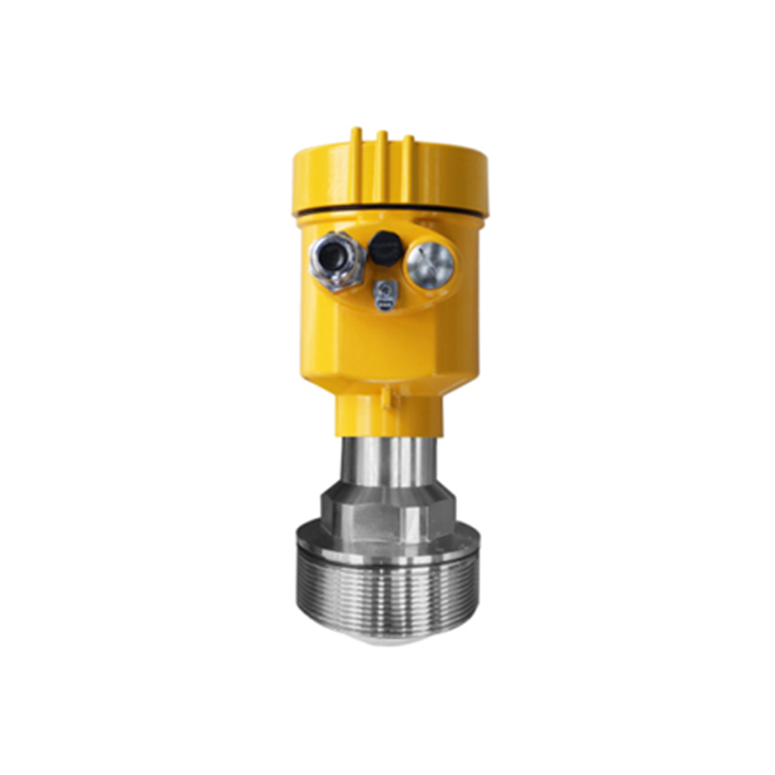
The METRAVON MV-RD13 extended-range 80 GHz radar level meter uses a 76 mm PTFE lens for liquid-level measurement. Its documentation describes 30 m and 150 m range configurations. Selecting the longer range requires checking the echo path and minimum surface distance; it is not simply a change to the full-scale value in the PLC.
What the Long-Range Configuration Changes
Radar measures the distance between its reference plane and the reflecting surface. The longest required distance usually occurs at the lowest liquid level. The shortest occurs at maximum fill. Establish both distances from the same reference plane and identify any difference between that plane, the tank roof and the process connection.
The 150 m figure is a configuration limit, not an assurance that every liquid, nozzle and surface condition will produce a usable echo at that distance. Foam, turbulence and low-reflectivity liquids require application review. For a bulk-solids silo, start with the MV-RD21 bulk-solids radar instead of assuming the liquid version is interchangeable.
MV-RD13 Lens, Range and Process Connection
| Item | Model data | Site notes |
|---|---|---|
| Measurement principle | 80 GHz FMCW radar | The output starts with a surface distance, from which configured level is calculated. |
| Range selection | 30 m or 150 m | Specify the required near and far limits on the order rather than only the maximum range. |
| Lens and beam | 76 mm PTFE; 3 degrees | A narrow beam still expands with distance and does not eliminate all off-axis reflections. |
| Nominal accuracy | +/-2 mm | The reference specification is not a tank-volume or long-distance site accuracy guarantee. |
| Connection choices | G3A thread or flange | Match the supplied drawing to the actual nozzle bore and mounting face. |
| Process temperature | Up to 150 deg C; version-dependent | The threaded version is listed to 130 deg C; review the selected assembly. |
| Model process-pressure interval | -0.1 to 1.0 MPa | Confirm the permissible pressure-temperature combination and the connection rating. |
Minimum measuring distance and flange size differ between documented configurations. Use the dimensioned selection and stated blind zone for the offered version, especially if a high-fill alarm is close to the antenna. Do not size the nozzle from an illustration alone.
Check the Path at Low Level, Not Just at the Roof
A clear opening immediately below the sensor is not enough for a tall vessel. Check the complete path past ladders, coils and other structures, including where the surface is lowest. Keep the filling stream outside the measurement path. A stilling pipe needs a separate assessment of its diameter, joints, openings and configuration; it is not automatically a compatible mounting accessory.
Commission the Distance Before Converting to Volume
Compare the radar distance with an independently established surface position, then check the configured level reference. Only after these agree should a controller or inventory system apply the tank-volume relationship. A tank strapping table or geometry model needs its own validation; increasing radar resolution cannot correct an incorrect vessel model.
Record performance near both operating extremes and during filling. Keep the echo information for troubleshooting. Excessive damping can hide a rapid change, while very short damping may reproduce waves or agitation. Select the response needed by the process and test the receiving system's response to signal loss.
Long-Range Application Questions
Q1. Does a 150 m version also measure down to zero distance?
No. The selected range has a near-field limit as well as a maximum distance. State the smallest expected air gap, including abnormal high level, and obtain the limit for the supplied version before deciding the high-level alarm location.
Q2. Will a 3-degree beam ignore an agitator?
Only the installation geometry and echo behaviour can establish whether the agitator interferes. The quoted angle describes the principal beam, not a hard boundary outside which reflection is impossible. Examine the signal with the agitator operating, not only when the tank is stationary.
Q3. Can the same cable carry analogue and serial outputs?
The manual describes separately powered configurations with 4-20 mA and RS485/Modbus using the required additional conductors. A two-wire HART loop is a different circuit. Match the cable cores, terminals and receiver to the ordered electronic unit rather than adding serial wiring to a standard loop.
Q4. Is the housing automatically IP67?
The selection distinguishes IP67 metal housings from an IP65 ABS option. The ordered enclosure and correctly sealed cable entries must suit the location. Neither rating replaces a chemical-compatibility assessment or approval for sustained immersion.
Send the Measurement Geometry With the Enquiry
Request an MV-RD13 range assessment with the liquid details, minimum and maximum surface distances, tank section, nozzle dimensions and required response. Add the PLC or DCS interface and any volume-conversion requirement. A quotation can then identify the antenna, range, connection and electronics as one configuration.
