


 Chinese
 Spanish
 Russian
 Portuguese
 French
 German
 Indonesian
 Thai
 Vietnamese
 Arabic
 Italian
 Turkish
 Polish
 Japanese



The METRAVON MV-RD12T 80 GHz radar water level meter measures from above the water with a PVDF lens assembly. It is an option for pumping stations, open-water monitoring and other sites where a submerged probe is difficult to maintain. Its distance reading becomes a useful water-level measurement only after the mounting reference and controller calculation have been established.
Establish the water-level datum
Survey the antenna reference plane against a staff gauge or another stable site datum. If the reference plane is H above that datum and the measured vertical distance is d, water level above the datum is H minus d. Keep the sign and units consistent in the local display, RTU and monitoring platform.
Check the mounting position after bracket work or replacement. Reusing an old offset after moving the antenna introduces a level error even when the radar distance measurement is correct. Record the reference height and instrument settings together so maintenance personnel can restore the installation.
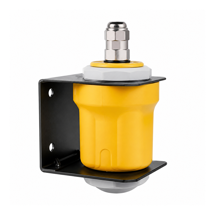
MV-RD12T range, housing and power selection
| Item | Product option | Site check |
|---|---|---|
| Radar frequency | 80 GHz | Non-contact distance measurement through an unobstructed air path. |
| Antenna | 42 mm PVDF lens assembly | Check compatibility with vapour, splashes and any cleaning chemicals. |
| Maximum range | Up to 50 m | Specify the required near limit and accuracy over the actual span; these depend on the version. |
| Process conditions | Atmospheric; -40 to 80 deg C | Not a pressure-vessel selection based solely on the water-level designation. |
| Enclosure protection | IP68 configuration | The supplied assembly and cable sealing must meet the agreed installation conditions. |
| Power and output | RS485 or analogue electronics options | Select the electrical version before calculating the power budget or specifying an RTU input. |
The available electrical arrangements include 9-28 V DC with RS485/Modbus, 12-24 V DC with 4-20 mA plus RS485, and 24 V DC two-wire 4-20 mA/HART. A 3.6 V low-power option is also listed. These are ordering alternatives, not four interchangeable supplies for a single unit. Obtain the terminal diagram and operating-current requirements for the selected electronics.
Battery stations need more than a low-power label
For solar or battery-powered monitoring, specify how often the station must take and transmit a valid reading. Include instrument start-up, measurement and communication time in the duty cycle. A controller that removes power too early may record a default or stale value instead of a completed measurement.
Separate sensor consumption from the radio, cellular modem and RTU loads. Cable voltage drop and cold-weather battery performance also affect the voltage available at the instrument. Request the selected version's current profile before sizing storage; a single nominal current is insufficient for a duty-cycled station.
Operation in wet and turbulent locations
Place the beam away from falling water, dense foam, structural edges and pump discharge turbulence where possible. Inspect for persistent condensation or deposits on the antenna. IP68 describes enclosure protection under specified test conditions; it does not mean the radar can continue normal water-level measurement while the antenna is submerged.
If the required low-water distance exceeds the selected 80 GHz unit's range, compare the MV-RD12T-120G range configurations. The replacement still needs its own near-distance, power and communications checks.
Water monitoring questions
Q1. Why does the radar disagree with the staff gauge by a constant amount?
Check the reference height and datum first, then compare the raw distance. A constant offset can come from a mismatched zero point rather than a faulty distance sensor. Do not adjust the measurement simply to match a gauge until both references have been surveyed.
Q2. Is IP68 sufficient for a flood-prone installation?
The flood duration, depth, cable joints and enclosure variant still need review. Put electrical joints above the expected flood level where practical. Define how the station flags readings during inundation and how the mounting reference will be checked afterward.
Q3. What should an RTU integrator request?
Request the exact protocol revision, register definitions, scaling, invalid-reading codes and timing requirements. Test a known level and a communication failure at the RTU, not just with a configuration tool. Send these requirements with the supply voltage, measuring distances and mounting sketch when requesting a quotation.
