


 Chinese
 Spanish
 Russian
 Portuguese
 French
 German
 Indonesian
 Thai
 Vietnamese
 Arabic
 Italian
 Turkish
 Polish
 Japanese



The METRAVON MV-RD12T-120G is a 120 GHz radar water level meter for non-contact measurements above an open water surface. Its range configurations include 30 m and 90 m options. The longer configuration can accommodate a greater antenna-to-water distance, but frequency and maximum range alone do not determine whether a monitoring site will produce dependable readings.
Define the distance interval, not just the channel depth
A sensor mounted high on a bridge must measure the distance from that mounting point to low water. The depth of water in the channel may be much smaller. At the opposite extreme, flood water must not enter the selected instrument's near zone or reach the antenna.
Use a surveyed cross-section and mounting elevation to describe both extremes. Include piers, bridge members, cable runs and vegetation that can obstruct the path. The beam covers a larger area as distance increases, so clearance close to the antenna is not enough to establish clearance at the lowest surface.
MV-RD12T-120G selection data
| Item | Option | Before ordering |
|---|---|---|
| Measurement frequency | 120 GHz | Confirm the required water-level application and mounting geometry. |
| Range options | 30 m / 90 m | Specify minimum and maximum antenna-to-water distance; do not assume every unit has a 90 m span. |
| Antenna material | PVDF; 42 mm assembly | Assess the water chemistry, vapour exposure and cleaning method. |
| Installation | G2 A / flange option | Check the actual mounting drawing, support and antenna reference plane. |
| Operating conditions | Atmospheric; -40 to 80 deg C | Consider the local environment at the sensor, including direct heat exposure. |
| Protection | IP68 option | Agree the enclosure and cable-entry conditions for the site. |
Near distance, beam angle and accuracy are configuration-sensitive. Specify these for the exact supplied version rather than combining the shortest near distance, longest range and highest accuracy from different configurations. Commissioning should include the distances that matter to the project, particularly any alarm threshold near the high-water end.
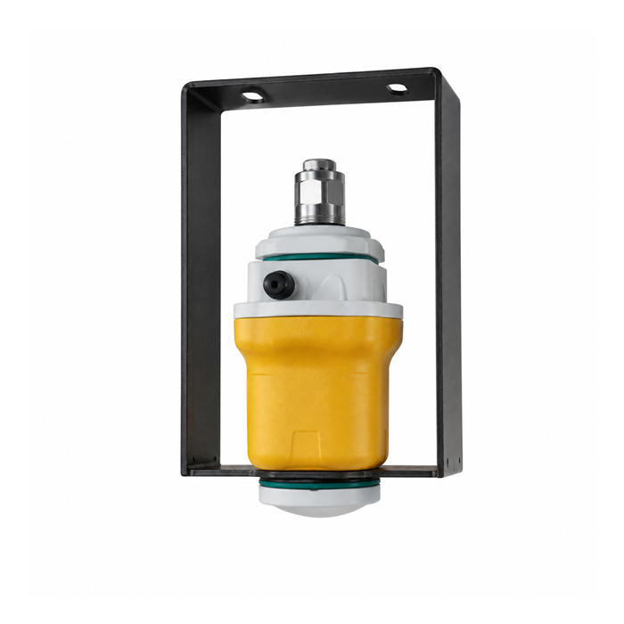
Replacing an 80 GHz water-level sensor
The MV-RD12T 80 GHz model and MV-RD12T-120G are separate selections. A higher frequency does not establish mechanical interchangeability, better results through foam or compatibility with the existing controller configuration.
For a replacement, compare the mounting dimensions and reference plane first, then the supply and output. Electrical options include RS485/Modbus, combined analogue and RS485, and a two-wire 4-20 mA/HART arrangement; the available supply depends on that choice. Do not reconnect an old cable by colour alone. Use the delivered unit's terminal diagram and update the station's offset if the reference plane changes.
Check the complete reporting chain
Test distance at the instrument, converted level at the logger and the final value on the remote platform. Verify units, timestamps and whether the platform displays current data or a retained last value. After a restart, the station should distinguish an unready measurement from a valid low-water reading.
Where measurements trigger flood alarms, agree the treatment of an invalid echo or communications loss before commissioning. A scheduled site visit should also check support movement, antenna contamination and changes in obstructions, rather than reviewing the digital reading alone.
Range and replacement questions
Q1. Should a 90 m version be chosen for every bridge?
No. Select it when the required distance and surface conditions justify that range. For a shorter installation, near-zone clearance, mounting stability and the required output may be more important. Provide the bridge elevation and water-level extremes so the range can be selected deliberately.
Q2. Can the device also provide river discharge?
A water-level reading alone does not establish discharge without a valid site relationship. If both surface velocity and level are required, review the MV-RD2480 open-channel flow meter and the surveying and calibration work that accompanies it.
Q3. What evidence should accompany an acceptance test?
Keep the instrument configuration, mounting reference, independent level readings and time-matched logger values. Test the alarm settings and a communication interruption. This record distinguishes a measurement problem from an offset, transmission or display problem when the station is serviced later.
Request the required version
Include the model MV-RD12T-120G, distance interval, mounting drawing, environment, power source and required reporting interval. For an existing station, add the controller and protocol information. State the accuracy needed over the actual operating span so the quotation identifies a testable configuration rather than only a maximum-range label.
