


 Chinese
 Spanish
 Russian
 Portuguese
 French
 German
 Indonesian
 Thai
Thai Vietnamese
 Arabic
 Italian
 Turkish
 Polish
 Japanese

selection summary
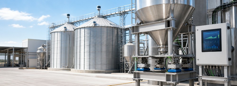
It is used for non-contact continuous level measurement of bulk materials, granular materials and powdery materials. The reference range is 0.3-150m. It is suitable for process conditions with high silos, small beam angles and purging interfaces. Before ordering, the material, measuring range, dust, material surface, installation port, temperature and pressure, explosion-proof and output should be confirmed as a set of conditions.
Product overview
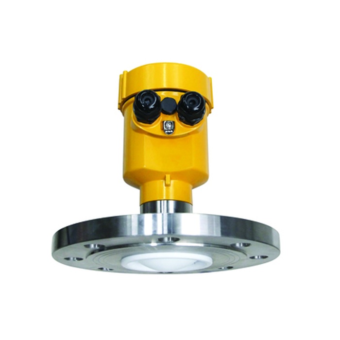
MV-RD21-120G 120 GHz radar level meter for bulk solids is used for non-contact continuous level measurement in industrial silos. It outputs continuous distance or level signals, which is suitable for inventory trends, material incoming and outgoing control, and high and low level warnings; it is not the same product as the level switch that only determines "material present/no material".
Measurement principle
The instrument emits a frequency modulated continuous wave signal from the top of the bin. After receiving the reflection from the material surface, it calculates the air height based on the frequency difference between the emission and the echo, and then combines the set bin height to convert the level. This series is classified as a 120 GHz product, and the operating frequency marked on the supplier's specification sheet is 123 GHz.
Applicable materials and usage scenarios
- Continuous measurement of high silos of powdery materials such as cement, fly ash, ore powder.
- Inventory trend monitoring of grain, feed, plastic particles and other granular materials.
- Non-contact measurement of bulk material silos such as coal, coke, ore.
- process conditions where there are many components in the silo, a narrow beam is required to avoid obstacles, or the antenna is prone to dust accumulation.
Value applied to procurement and technicians
Technical parameters
| Measuring medium | Solid: block material, granular material, powdery material |
|---|---|
| Measuring range | 0.3-150m |
| process connection | Flange≥DN80 |
| process temperature | -40~110℃ |
| process pressure | -0.1~0.3MPa |
| Measurement accuracy | ±5mm |
| Series/operating frequency | 120 GHz series; specification sheet marked 123 GHz |
| The beam horn. | 3° |
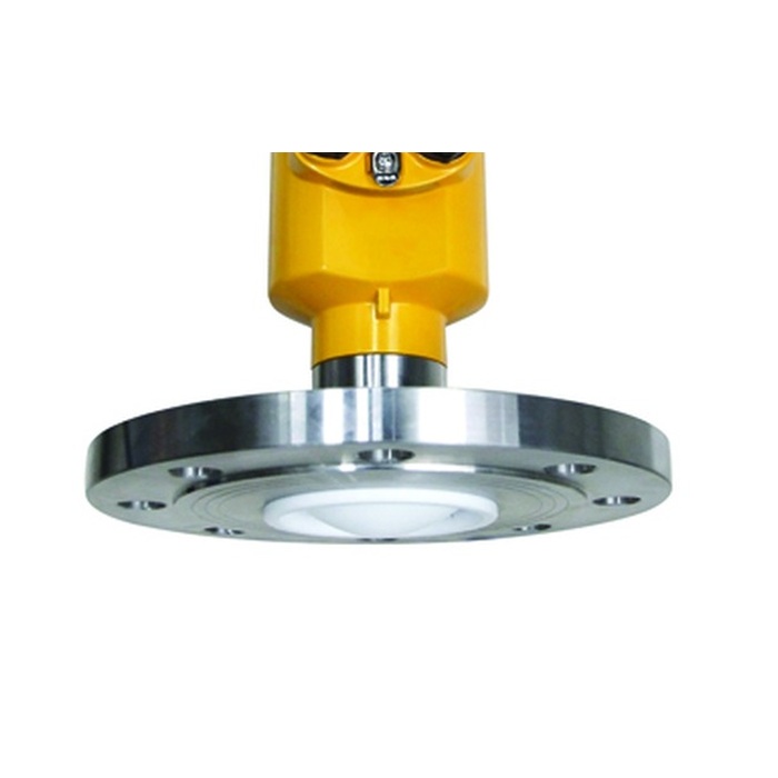
| antenna | 78mm PTFE lens antenna, optional purge interface |
| Protection level | IP67 |
| Signal output | Two-wire system 4-20mA/HART; four-wire system 4-20mA or RS485 Modbus |
| Electricity | Two-wire system DC24V; four-wire system DC12-24V or AC220V |
| Explosion proof | Optional Ex ia IIC T6 Ga or Ex d IIC T6 Gb, please confirm with complete model number and certificate |
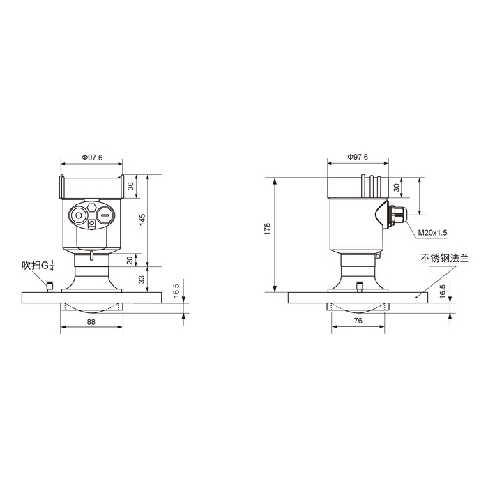
Note: The values on this page are used for inquiry and preliminary selection. Temperature, pressure, flange, antenna, housing, explosion-proof and output options need to be confirmed according to the complete configuration, and the upper limits cannot be combined by default.
Selection guide
- Provide material name, maximum particle size, stacking angle, dielectric properties, moisture content and dust conditions.
- Select the measuring range according to the effective distance from the empty silo to the highest level, and reserve blind areas and abnormal level margins.
- Submit the silo height, diameter, inlet, outlet and internal component diagrams, and check the 3° beam path.
- Confirm the clearance under the DN80 and above flange and antenna, and whether the purging interface and clean air source are required.
- Confirm normal and abnormal temperature, pressure, explosion-proof area and shell material as combined conditions.
- Unified power supply, 4-20mA/HART or RS485 Modbus, station number and control system access requirements.
Key points for installation and commissioning
- Avoid the feed beam, dust return flow and fixed components in the bin, and aim the antenna vertically at a representative material surface.
- The flange must be kept horizontal, and the installation short pipe and protective parts must not block the effective beam of the 78mm lens antenna.
- When purging is required, use a clean, dry air source that meets the requirements, and leave maintenance space for valves and pipelines.
- The short position establishes a fixed echo baseline, and then reviews the trend during the low, medium, and high levels and feed dust stages.
- The high-level stoppage must be taken into account the materials in transit in the conveyor belt, spiral or pneumatic pipeline, and the measured value cannot be directly equated to the stop point.
FAQ
What materials is MV-RD21-120G suitable for?
Suitable for continuous level measurement of block, granular and powdery solid materials. Particle size, dielectric properties, dust, moisture content and material surface inclination angle must still be provided when selecting.
What is the measuring range of MV-RD21-120G?
The data reference range is 0.3-150m. The effective range should deduct the blind area and leave margin for the highest level, abnormal stacking and installation height.
Why is the 120 GHz series marked with 123 GHz?
The supplier classifies this product into the 120 GHz series, and the specification sheet indicates the operating frequency is 123 GHz. The page retains both calibers at the same time, and it is recommended that the purchasing documents indicate the complete model number and frequency of the specification sheet.
What is the value of a 3° beam angle?
A narrower beam helps avoid silo walls, reinforcement ribs and feeding facilities, and is also easier to align with local material surfaces; wrong measurement points will still cause representative deviations.
Is it necessary to select the purge interface?
No. It should be determined based on the dust accumulation speed of the material, antenna structure, air source quality and maintenance cycle. Purging is not a substitute for avoiding feed flushing and periodic inspections.
Can the silo tonnage be calculated directly?
What radar measures is distance or level. The tonnage also requires the silo geometry, material surface shape and packing density. Changes in powder density will bring additional errors.
Can it be connected to PLC or DCS?
Optional 4-20mA/HART or RS485 Modbus. Before connecting, confirm the power supply, signal isolation, station number, baud rate, upper and lower range limits and fault output.
What is the most important thing when installing a high silo?
The measuring point should avoid the feed beam, so that the beam covers a representative material surface, and ensure that the installation of short pipes, protective parts and purge parts does not block the antenna.
Will the dust environment cause wave loss?
High-frequency narrow beams are beneficial to solid measurement, but extremely dense dust, antenna dust and tilted material surfaces will still weaken the echo and should be verified during the actual feeding stage.
Inquiry What to provide for MV-RD21-120G?
Provide materials, particle size, silo height and diameter, material inlet and outlet positions, dust, temperature and pressure, explosion-proof, installation flange, purge air source, power supply output and on-site diagram.
Ordering instructions
When ordering, please provide the material name and form, particle size and dust, bin size, material inlet and outlet location, measuring range, normal and abnormal temperature and pressure, process connection, hazardous area, power supply, output protocol, on-site photos and control purposes. The final parameters are subject to the written selection confirmation and order drawing.
